KT-210-4 27
Description of the control characteristic, see chapter
Operating modes, page 27.
• Connect the auxiliary relay of the FI (K8) to the ter-
minals 4 and 6. Use shielded cables for this, gold-
plated contacts are recommended.
• Connect the FI fault reset button (S4) to the termin-
als 3 and 6. Use shielded cables for this. Gold-plated
contacts are recommended.
Wiring the terminal strip X102 (fault message relay)
according to the schematic wiring diagram (see
chapter Schematic wiring diagram, page 28).
Connecting the terminal strip X100 (data
communication)
WARNING
Risk of FI failure!
Never apply any voltage to the terminal strip
X100, not even for test purposes!
The terminal strip X100 provides a communication in-
terface for:
• BEST SOFTWARE with interface converter
• RS485
Further information on BEST SOFTWARE, see chapter
Data communication with the FI, page 30.
Terminal assignment X100:
• Terminal 1: PRS485
• Terminal 2: NRS485
• Terminal 3: N/A
• Terminal 4: 0V DC
4.2 Operating modes
The compressor FI unit is controlled by superior con-
trollers (schematic wiring diagram, positions B1 and
B3). In this application, the FI can be operated with the
factory-set parameters.
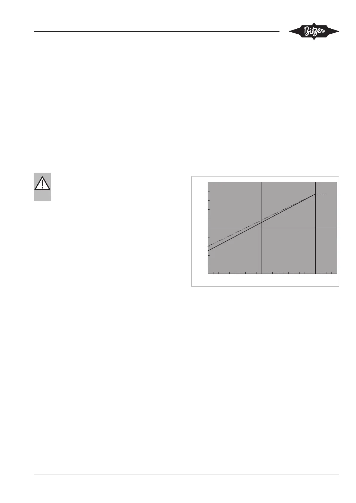
Preprogrammed control characteristics
Two standard control characteristics are prepro-
grammed in the FI (see figure 7, page 27 and see fig-
ure 8, page 28). Depending on the terminals chosen
for the control signal cables on the terminal strip X101
in the FI housing, one of these control characteristics
can be selected.
• Voltage-dependent control characteristic analogue
signal 0 ..10V, terminals 2 and 8.
100
0
90
80
70
60
50
40
30
20
10
0 1 2 3 4 5 6 7 8 9 10 12
0
f [Hz]
U [V]
0 .. 10 V
Fig.7: Steuercharakteristik 0 .. 10 V, gestrichelte Linie 2-Zylinderver-
dichter, durchgezogene Linie 4-Zylinderverdichter
• Current-dependent control characteristic analogue
signal 4 ..20mA, terminals 1 and 8.
 Loading...