CB-100-218
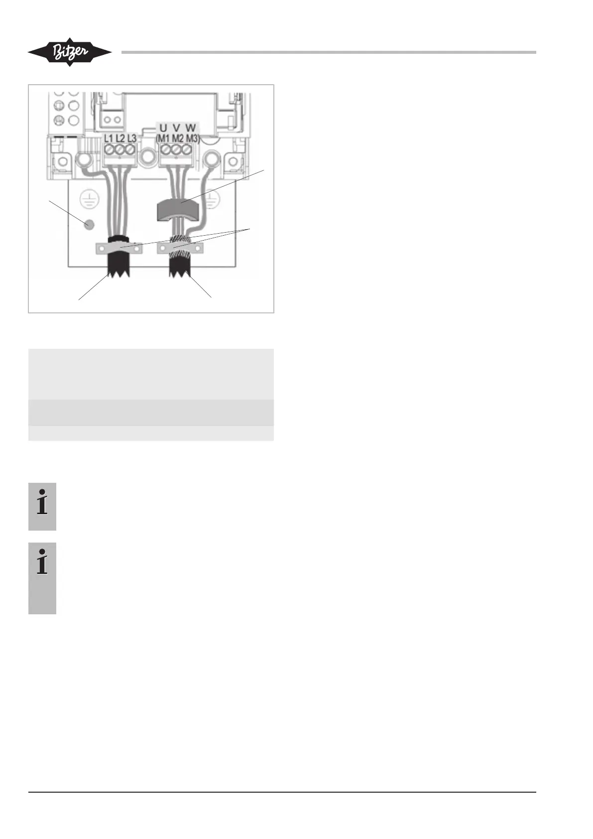
Fig.11: Power connections (voltage supply cable and motor cable)
with fixture
A Earth connection B voltage supply
cable / terminals for
nominal supply
voltage
C Motor cable / motor
terminals
D Cable clips
E Ferrite core
5.3 Control connections (inputs and outputs)
Information
To meet the EMC and safety requirements, the
control module must be connected to the pro-
tective earth conductor outside the device!
Information
The entire external wiring must be approved for
maximum system voltage!
All control and signal terminals guarantee safety
extra low voltages (SELV), i.e., they are protec-
ted by double insulation.
Specification of the control connections:
• Cables completely without or with non-insulated wire
end sleeves: 0.25..1.5 mm².
• Cables with insulated wire end sleeves: 0.25..0.75
mm².
Digital inputs
• Function
– X13:2:DI1 (Start)
Compressor start command.
– X13:3:DI2 (Force)
Operation of the compressor at a minimum fre-
quency of 50Hz.
– X13:4:DI3 (p01 → 2)
External control: without function.
With extension module: Switch over from evapor-
ation temperature setpoint 1 to 2.
– X12:1:DI4 (pc1 → 2)
External control: without function.
With extension module: Switch over from con-
densing temperature setpoint 1 to 2.
– X12:2:DI5 (Reset)
Reset of faults.
– X12:3:DI6 (Detection)
Automatic detection of the extension module.
• Technical data
– Status:
Off: 0..5V DC
Undefined: 5..15 V DC
On: 15..24V DC
– Max. input voltage: ±30V DC
– Input impedance: 3,3kΩ.
– Input current: 7.3mA ±10% at 24VDC
– Common on X10:4
Analogue inputs
• Function
– X11:1:AI1 (mA/p0)
External control: Setpoint as 4..20mA signal.
X10: 2: Common
With extension module: Input for low pressure
coming from the extension module (→X11:1)
– X11:2:AI2 (V/pc)
External control: Setpoint as 0..10 V signal
X10: 2: Common
With extension module: Input for high pressure
coming from the extension module (→X11:2)
• Technical data
– Input signal: 0..10V or 4..20 mA