CB-100-2 21
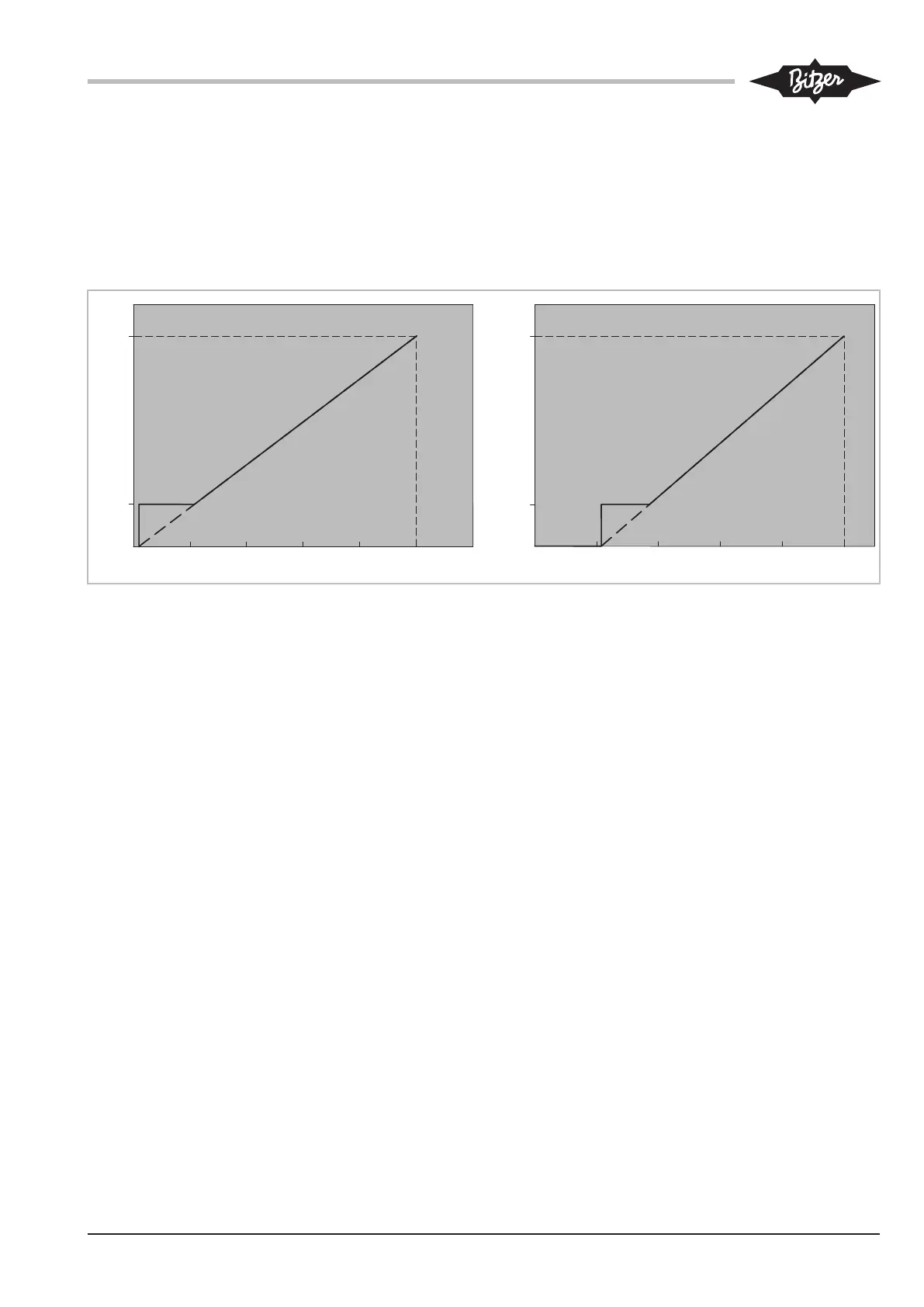
"0..Max" control characteristic
Alternatively, the "Min..Max" control characteristic can
be switched to "0..Max" by a change in parameter.
• In the "0..Max" control characteristic, in addition to
the DI1 (X13: 2) start command, a setpoint signal of
> 1% (0.1V) is required for starting the compressor.
The setpoint signal presets the frequency to a value
between 0Hz and the maximum frequency. If the
signal is >1% but lower than the minimum frequency
of the compressor, the compressor will run at the
minimum frequency.
Graphical explanation of the "0..Max" control charac-
teristic, see figure 13, page 21.
0
f [Hz]
I [mA]
8 12 16 20
4 .. 20 mA
f [Hz]
0 2 4 6 8 10 12
U [V]
0 .. 10 V
f
max
f
min
f
max
f
min
0,1
1%
4,16
1%
4
Fig.13: "0..Max" control characteristic
5.4.2 Capacity control of the compressor as a
function of the evaporation pressure
To control the capacity of the compressor as a function
of the evaporation pressure will require the optional ex-
tension module for pressure control.
Installation of the extension module kit (part number
34797201):
• Plug the extension module into the top slot of the FI
control module and tighten the screw.
• Ratiometric pressure transmitter
– Install the pressure transmitter labelled
"2CP5-71-49" on the low pressure side.
– Install the pressure transmitter labelled
"2CP5-71-47" on the high pressure side.
– In the case of Schrader valves, install the pres-
sure transmitters without a copper gasket ring to
ensure safe opening.
For the wiring of the extension module, see chapter
Schematic wiring diagrams semi-hermetic reciprocating
compressors, page 26.
Function and technical data of the extension module
• X1:1, 2 and 3
– Input for ratiometric low pressure transmitter.
– Correct function is indicated by blue LED.
• X1:4, 5 and 6
– Input for ratiometric high-pressure transmitter
– Correct function is indicated by red LED.
• X2:1
– Analogue output for transmitting the low-pressure
value to the FI (X11:1:AI1).
• X2:2
– Analogue output for transmitting the high-pressure
value to the FI (X11:2:AI2).
• X3:1
– Input for 24VDC power supply coming from the
FI (X12:5).
• X3:2, 3, 4, 5 and 6
– 24V= outputs.
– Allow simple wiring of the digital inputs of the fre-
quency inverter.
• X4:4
– Digital output for automatic detection of the exten-
sion module by the frequency inverter
(X12:3:DI6).