CB-100-220
5.4 Operating modes
The VARIPACK frequency inverter can be operated in
two different operating modes:
• Capacity control of the compressor depending on an
external setpoint signal (see chapter Capacity con-
trol of the compressor depending on an external set-
point signal, page 20).
• Capacity control of the compressor depending on the
evaporation pressure, which will require the optional
extension module for pressure control (see chapter
Capacity control of the compressor as a function of
the evaporation pressure, page 21).
In addition to direct evaporation pressure control, the
condenser fan can also be controlled via a 0..10V
output signal and a second compressor can be connec-
ted.
5.4.1 Capacity control of the compressor depending
on an external setpoint signal
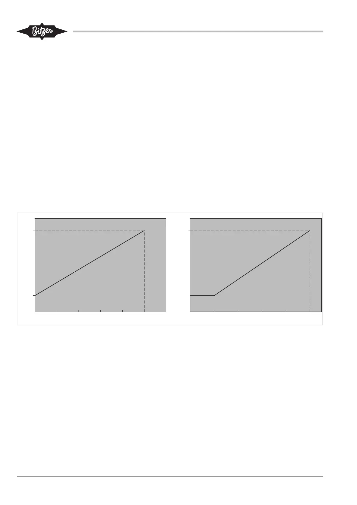
"Min..Max" control characteristic
The VARIPACK frequency inverters can be activated
without change in parameters by a0..10V or
4..20mA signal according to the "Min..Max" control
characteristic.
• In the "Min..Max" control characteristic, the com-
pressor will start as soon as the DI1 (X13: 2) start
command is given. The setpoint signal will control
the frequency linearly between the minimum and
maximum frequencies of the compressor.
– If a 0..10V signal is used, it must be connected
to the input AI2 (X11:2).
– If a 4..20mA signal is used, it must be connec-
ted to the input AI1 (X11:1).
Graphical explanation of the "Min..Max" control char-
acteristic, see figure 12, page 20.
0
f [Hz]
I [mA]
4 8 12 16 20
4 .. 20 mA
f [Hz]
0 2 4 6 8 10 12
0
U [V]
0 .. 10 V
f
max
f
min
f
max
f
min
Fig.12: "Min..Max" control characteristic


 To Next Page