29
GPIB
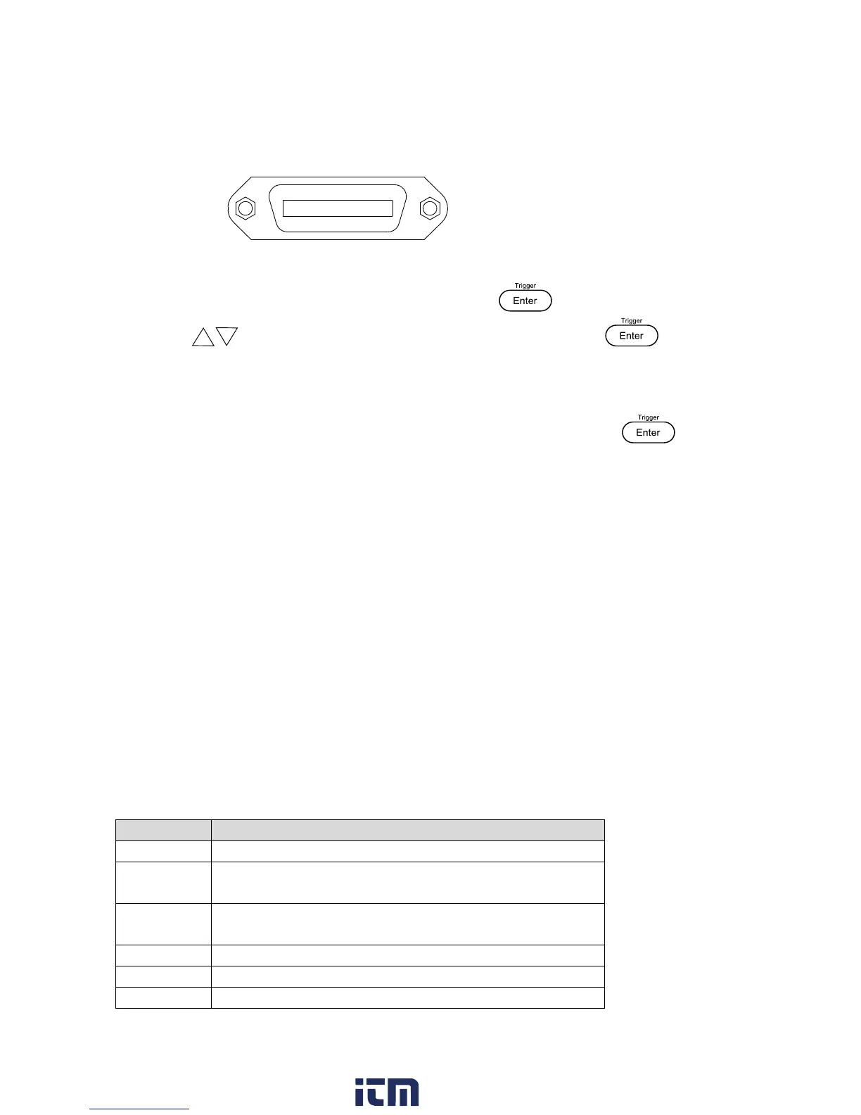
Each model can be configured with a GPIB address from 1-30. To communicate via GPIB,
connect a GPIB cable to the GPIB interface on the rear panel, as illustrated below.
Follow the instructions below to select and configure the GPIB interface for remote operation.
1. From the SYST SET menu, select COMM and press .
2. Press keys or rotary knob until GPIB is displayed and press to configure
the settings for GPIB remote communication.
3. Configure the GPIB Address to which the power supply will be assigned to. Use the
rotary knob or numeric keypad to enter a value from 1-30 and press .
4. Make sure the address assigned to the power supply unit matches the address the data
commands are being sent to.
5 Remote Commands
5.1 Parameter Definition
The 9200 Series power supplies support communication protocols, which include standard SCPI
commands and a few proprietary commands that follow the SCPI convention. The SCPI interface
enables users to operate the power supply through a computer or a terminal equipped with
IEEE-488.2 GPIB, RS-232, or USB interface. SCPI IEEE-488.2 also supports multi-unit control
allowing a user to control up to 32 power supplies.
The following table lists all of the numerical parameters.
Boolean value, can be 1 or “ON”, 0 or “OFF”
Integer value, can be zero, positive or negative
integer number
Flexible numerical value, can be zero, positive or
negative float point numeric value
String value, characters enclosed in single or double
quotes
w ww . . co m
information@itm.com1.800.561.8187