BK RADIO Page 4-1
SECTION IV
THEORY OF OPERATION
4.1 INTRODUCTION
This section contains the theory of operation for the BK Radio GPH-CMD radio. To help you understand
the operation of the equipment, refer to the schematic diagrams in Section VI of this manual.
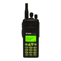
4.2 DESCRIPTION
The GPH-CMD radios are self-contained VHF FM Radios covering the frequency range of 136 MHz to
174MHz. The radios are multi-channel and digitally synthesized using a single crystal for frequency
control. All models incorporate an EEPROM for the storage of Channel Frequency, Code Guard™, and
Dual Tone Multiple Frequency/Automatic Numeric Identifier (DTMF/ANI) encode information. All models
also include low-battery and busy-channel indicators. Toggle switches can be programmed to control
Hi/Low Transmit Power, Channel Scan, Priority Scan, Repeater Talk-Around, and Group Scan. Status
and channel information is displayed over a liquid crystal display Connectors are provided on the side of
the unit for an external antenna, microphone, speaker, and other optional accessories. A variety of twist-
off battery packs are also available.
4.3 THEORY OF OPERATION
Circuitry for the GPH-CMD Series radio comprises five major circuits:
• The RECEIVER, which consists of RF Preselectors, RF Preamplifier, Mixer, IF Filters, IF Amplifiers,
FM IF IC, and Noise Squelch circuitry.
• The TRANSMITTER, which consists of a Power Amplifier, Harmonic Filter, Antenna Switch, and
Power Control circuitry.
• The SYNTHESIZER, which consists of a Voltage Controlled Oscillator (VCO), VCO Buffer,
Synthesizer Buffer, Synthesizer IC, Temperature Compensated Crystal Oscillator (TCXO)
Reference, Loop Filter, VCO Coarse Tune Adaptive Filter, 3.0V and 4.5V Voltage Regulators.
• The SYSTEMS area, which consists of a Microprocessor, EEPROM, VCO Coarse Tune, Front End
Tuning and Power Set, 3.3V Regulator, 5V Regulator, -15V Regulator, 7.0V Regulator and Low-
Battery Shutdown, Receive Audio, Deviation Compensation and Squelch Adjustment.
• The DIGITAL SIGNAL PROCESSING (DSP) area, which consists of a Digital Signal Processor,
Flash Memory, CODEC, TCXO, 1.5V and 3.3V Voltage Regulators.
4.3.1 RECEIVER
The Receiver is a dual-conversion design with intermediate frequencies of 16.9 MHz and 455 kHz. RF
signals received at the antenna pass through the Antenna Switch and Front End. The Front End consists
of an amplifier and two Microprocessor-tuned bandpass filters. The Front End amplifies the receive
frequency and attenuates image, half IF, and other frequencies that degrade Receiver performance.
 Loading...