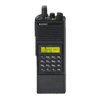
Maintenance GPH-CMD VHF Radio
Page 5-4 BK RADIO
5.3.3 REPAIR
This section describes the procedure along with any special techniques for replacing damaged or
defective components.
A. Connectors
When replacing a connector, refer to the appropriate PC board assembly drawing and
follow the notes to ensure correct mounting and mating of each connector.
B. Crystal
The use of any other than a BK Radio crystal is considered an unauthorized modification.
C. Diodes
Use caution when soldering since excessive heat can damage the diode. Note the diode
polarity before removal.
D. Integrated Circuits
Refer to Appendix A for mounting and soldering instructions.
E. Wiring/Coaxial Cable
When repairing a wire that has broken from its terminal, remove all old solder and pieces of
wire from the terminal, restrip the wire to the necessary length, and resolder the wire to the
terminal. Replace a damaged wire or coax with one of the same type, size, and length.
5.4 DISASSEMBLY/ASSEMBLY
5.4.1 BATTERY REMOVAL
To remove the battery pack, turn the radio off. Press up the metal tab on the side of the case
while turning the pack approximately 30°. Remove the pack from the radio.
5.4.2 UNIT DISASSEMBLY
A. Covers
1. Remove the four screws from the radio rear cover (the side opposite the speaker grill).
2. Remove the two screws holding the heat sink shield to the rear cover, and remove the
heat sink shield.
3. Loosen the PTT housing screw and separate the front cover from the main frame.

 Loading...