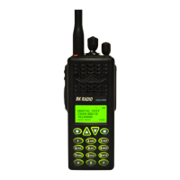
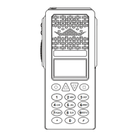
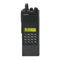
GPH-CMD VHF Radio Maintenance
BK RADIO Page 5-5
B. Options Board and Keyboard
1. Disconnect the zero insertion force connector J10 from the Options board by sliding the
connector sleeve toward the top of the radio. This allows the flex cable to be
unplugged.
2. Remove the five screws that secure the Options board to the keyboard and the front
cover, and unplug the keyboard.
C. RX/TX Board
1. Unfasten the three retaining clip screws that secure the RX/TX board to the main
frame.
2. Carefully remove the antenna coax from the RX/TX connector.
3. Lift up on the RX/TX board until it is disconnected from the Systems board.
D. Synthesizer and VCO
Remove the screw and unsolder the five tabs that secure the Synthesizer shield to the
Systems board. Remove the shield halves from both sides of the Systems board.
E. Top Plate and Switch Board
1. Remove the channel select, volume, and the squelch knobs.
2. Remove the retaining fasteners from the channel select switch, volume control, and the
squelch control.
3. Remove the bezel and inlay, retaining the channel select stop pins (if used).
4. Unfasten the four screws that secure the top frame assembly to the main frame (the
screws are located on the side of the frame, two screws beside the channel select
switch and two screws below the PTT housing).
5. Unsolder the audio jack wire from Systems board location E13.
5.4.3 ASSEMBLY
To assemble the unit, complete the disassembly procedure in reverse order.
 Loading...