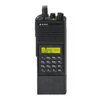
Theory of Operation GPH-CMD VHF Radio
Page 4-6 BK RADIO
A. Voltage Controlled Oscillator (VCO)
Transistor Q4 provides the gain, and an L-C resonant tank circuit provides the frequency selectivity
and phase shift necessary to produce an oscillator. Frequency control of the oscillator is
accomplished by the tuning tank circuit comprised of mechanically adjustable transformer T1 and
varactors CR4 and CR5. The cathode of CR4, connected to the Loop Filter, is used to lock the
VCO to the desired carrier frequency. The anode of CR4, connected to the Coarse Tune Adaptive
Filter, is used to pre-tune the VCO frequency within the lock range of the synthesizer. CR5 is
used in the Transmit Mode to modulate the carrier. The oscillator frequency range is 136-174 MHz
in the Transmit Mode and 119.1-157.1 MHz in the Receive Mode (low side injection). The 16.9
MHz shift from receive to transmit is achieved by turning on PIN diode CR3, thus adding L4 to the
tank circuit. Q5 and associated circuitry provide additional power supply filtering for the VCO.
Diode CR6 gives the filter a rapid power up response while maintaining a very low cutoff
frequency.
B. VCO Buffer
The VCO Buffer is a cascode configuration with bipolar transistor Q3 feeding common gate FET
Q21. It isolates the VCO from the Receiver/Transmitter circuitry and provides enough power gain
to supply a nominal level of +7 dBm in receive and +5 dBm in transmit.
C. Synthesizer Buffer
Synthesizer Buffer Q2 provides isolation between the Synthesizer IC and Receiver/Transmitter
circuitry and additional isolation between the Synthesizer IC and the VCO.
D. Synthesizer IC
Synthesizer chip U6 contains a 5-bit integer reference divider and a main divider controlled by an
18-bit delta-sigma modulator. The delta-sigma fractional-N capability permits very fine frequency
resolution while using a very high phase detector sample rate. The charge pump phase detector
provides current pulses at the sample rate whose polarity and width are proportional to the phase
error between the divided reference and the divided VCO. The phase detector gain is
programmable and is adjusted across the operating frequency band to compensate for changes in
VCO steering line sensitivity. A separate frequency steering output is available from U6 that
provides a low resistance connection to either the 4.5V supply or ground if a significant frequency
error exists. In a locked condition, the frequency steering output is high impedance. U6 also
contains a direct digital modulation register that allows modulation signals within the bandwidth of
the phase locked loop to be applied to the VCO by writing samples to the register.
E. TCXO Reference
The TCXO Reference, Y1, is a purchased module that provides ±2.5ppm stability over a
temperature range extending from -30°C to +60°C. The direct digital modulation register within U6
eliminates the need to pull the frequency of the Reference Oscillator in order to apply low
frequency modulation to the VCO.
F. Loop Filter
The Loop Filter converts the phase detector current pulses into a filtered voltage that adjusts the
VCO frequency in a direction to maintain phase and frequency lock between the divided reference
and the divided VCO. The frequency steering output of U6 is summed into the Loop Filter to
reduce lock time when a significant change in VCO steering line voltage is required for a new
programmed frequency.

 Loading...