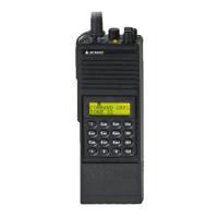
Theory of Operation GPH-CMD VHF Radio
Page 4-8 BK RADIO
D. Front End Tuning and Power Set
D/A converter U2 and amplifier U10-B allow the Microprocessor to set the Front End Tuning
voltage in Receive Mode and the Power Set voltage in Transmit Mode to any value in the range of
0V to -15V.
E. 3.3V Regulator
U14 provides a regulated 3.3V supply for the Microprocessor and other digital circuitry in the radio.
F. 5V Regulator
U8 provides a regulated 5V supply for the Receiver and other analog circuitry in the radio.
G. 7.0V Regulator and Low-Battery Shutdown
A 7.0V Regulator is composed of U3, Q10, and associated circuitry. Regulator operation is
monitored via Q11. The Microprocessor will shut down radio operation if a low-battery or 7.0V
short circuit occurs. Q1 is used to switch the regulator off during Battery-Saver Mode.
H. -15V Regulator
U5, L8 and associated circuitry comprise a -15V switching regulator. Q25 is used to switch the
regulator off during Battery-Saver Mode.
I. Receive Audio
U9 is a 0.5 Watt Audio amplifier. Muting is controlled by the Microprocessor. The audio level out
of U9 is controlled by the analog potentiometer connected to the Volume Knob, R51.
J. Deviation Compensation
The transmit Deviation Compensation is accomplished by one of the two digital potentiometers in
U16. At higher Transmitter frequencies, less voltage is needed for VCO modulation, so this circuit
attenuates the signal. Also, when Code Guard tones are being transmitted, the deviation sensitivity
is reduced so that overall deviation remains constant.
K. Squelch Adjustment
The second digital potentiometer in U16 provides programmable attenuation between the
discriminator audio output of the Receiver and the squelch threshold detection circuit of the
Receiver. The Microprocessor reads the voltage on the wiper of the analog potentiometer
connected to the Squelch Knob, R85, to determine the desired Squelch Level and programs U16
so that the desired threshold level is achieved.
.

 Loading...