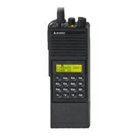
GPH-CMD VHF Radio Maintenance
BK RADIO Page 5-9
F. Receiver Front End Tuning
Bandpass filters in the receiver front end are manually tuned to optimize reception at 136
MHz. If components in the bandpass filters, RF amplifier, or mixer are replaced this
adjustment may be necessary to maintain specified RF sensitivity.
As the inductors of the bandpass filters are manually tuned, the passband is aligned with
the incoming RF carrier, optimizing sensitivity.
To perform the adjustment:
1. Program 136 MHz receive frequency, wideband (25/30 kHz) mode. Turn the
monitor/squelch control fully clockwise. Adjust the volume control to mid range.
2. Connect an RF signal generator tuned to 136 MHz to the antenna jack of the radio.
Modulate the generator with a 1 kHz tone at 3 kHz deviation.
3. Connect a distortion analyzer to the radio speaker output.
4. Adjust the RF signal generator level to obtain a SINAD reading between 6 and 12 dB
on the distortion analyzer.
5. Adjust L2, L3, L4, and L5 alternately to obtain the best SINAD reading. If necessary
reduce the signal generator level to maintain a SINAD reading between 6 and 12 dB.
G. Receiver Front End Slope
Bandpass filters in the receiver front end are electronically tuned to optimize reception
above 136 MHz. The tuning is customized using the receiver front end slope adjustment. If
components in the bandpass filters, RF amplifier, or mixer are replaced this adjustment
may be necessary to maintain specified RF sensitivity.
Four varactors are used in the receiver front end bandpass filters. The control voltage for
these varactors changes to accommodate different receiver frequencies. The proper value
is determined by microprocessor U1 (Systems board) using data stored in non-volatile
memory. The voltage from DA converter U2 (Systems board) is amplified and applied to the
varactors.
To perform the adjustment:
1. Program 174 MHz receive frequency, wideband (25/30 kHz) mode. Turn the
monitor/squelch control fully clockwise. Adjust the volume control to mid range.
2. Connect an RF signal generator tuned to 174 MHz to the antenna jack of the radio.
Modulate the generator with a 1 kHz tone at 3 kHz deviation.
3. Connect a distortion analyzer to the radio speaker output.
4. Adjust the RF signal generator level to obtain a SINAD reading between 6 and 12 dB
on the distortion analyzer.
5. Follow the instructions for Receiver Front End in the GPH-CMD Editor Software. If
necessary reduce the signal generator level to maintain a SINAD reading between 6
and 12 dB.

 Loading...