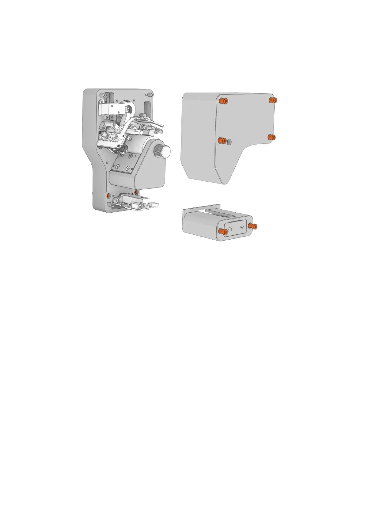
3 Remove the upper and lower covers from the Audio and KeyKode Reader by
unscrewing the 6 x M3 screws with a 2.5mm Allen key. The screws are ‘captive’ so they
remain attached to the reader. Removing the covers gives you access to the captive
screws needed to attach the reader to your Cintel scanner.
Remove the upper and lower covers from the reader by unscrewing the six M3
cover screws. As they are captive screws, you only need to unscrew them a
short distance until they release contact, as shown in the image above.
4 Remove the four M4 screw plugs from your Cintel scanner using a 2mm Allenkey.
Thecorrect screws are the top left screw, and bottom two screws located beneath the
left options interface XLR connector.
5 Mount the reader to your scanner by plugging its male XLR connector into the female
XLR left options interface connector on your Cintel scanner.
46Optional Audio andKeyKode Reader