Using Tally
24
Tally Port Pin Connections
It is not necessary to connect the tally port of SmartView or SmartScope and you can skip this section if you
do not intend to use the tally feature.
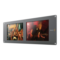
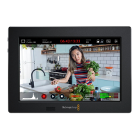
Each SmartView Duo and SmartScope Duo screen features independent tally borders in red, green or blue
which can be used to indicate the status of a video signal such as on-air, preview or recording.
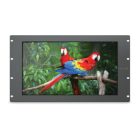
SmartView HD can also display a red, green or blue tally border.
The 9-pin D-sub tally port accepts contact closure signals from switchers and automation systems. Please
refer to the accompanying tally pin connections diagram for information about wiring the tally port for use
with your switcher or automation system.
The 9-pin D port wiring description is printed on the rear of the unit showing contact closures to display red,
green or blue tally borders on each independent monitor.
SmartView Duo and SmartScope Duo
Tally Pin Connections
Pin Function
1 Monitor 1 Red
2 Monitor 1 Green
3 Monitor 1 Blue
4 Ground
5 Ground
6 Ground
7 Monitor 2 Red
8 Monitor 2 Green
9 Monitor 2 Blue
SmartView HD Tally Pin Connections
Pin Function
1 Red
2 Green
3 Blue
4 Ground
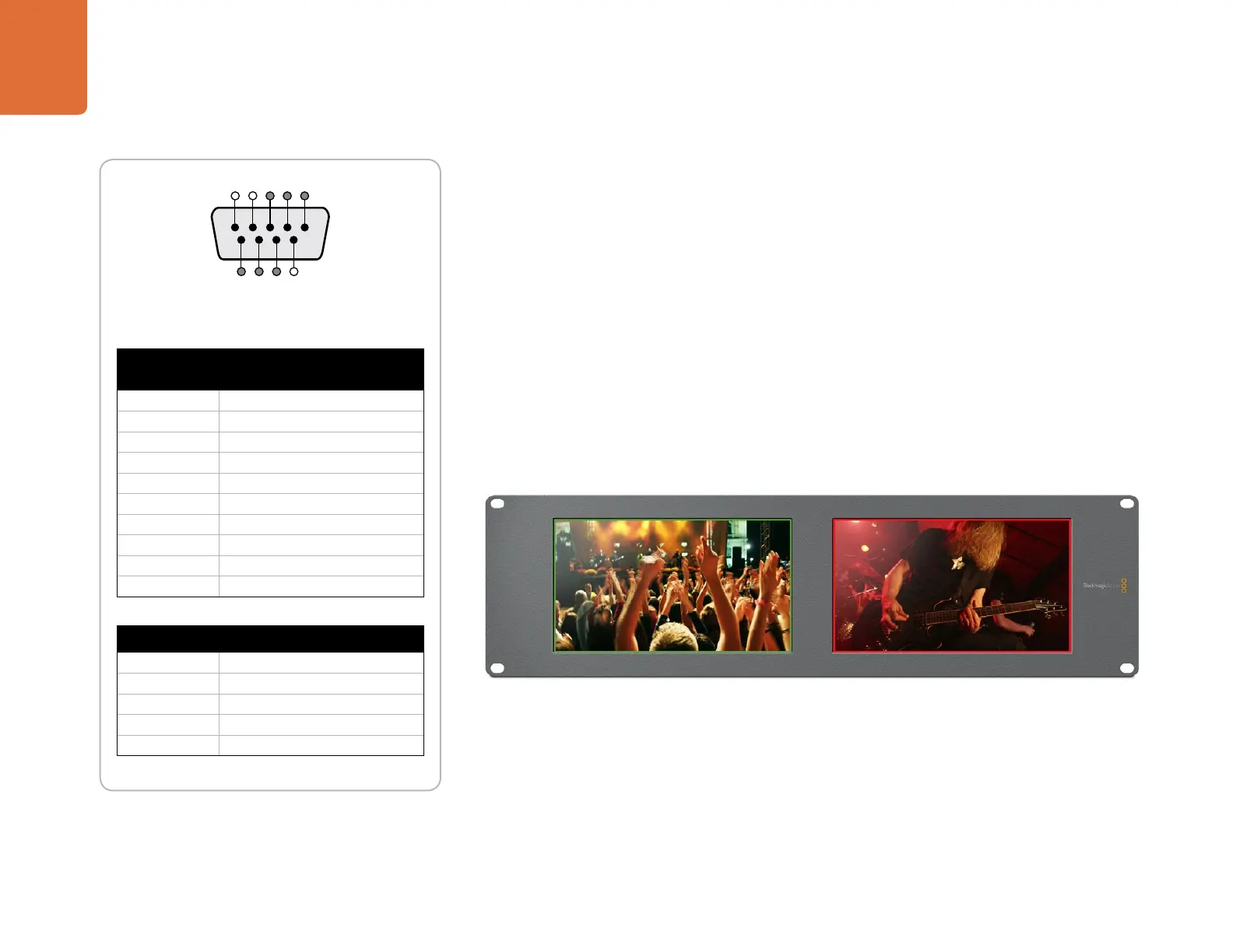
SmartView tally port
5 4 3 2 1
9 8 7 6
SmartView Duo showing green and red tally borders.