Page 8
LB Hex™ Unplugged Manual Rev. A © 2018 Blizzard Lighting, LLC
Fuse Replacement
LB Hex™ Unplugged utilizes a high-output switch-mode power supply with an
internal fuse. Under normal operating conditions, it should not require replace-
ment. Should the fuse require replacement, please contact us for instructions,
or to return your unit for service.
Connecting A Bunch of LB Hex™ Unplugged Fixtures
You will need a serial data link to run light shows using a DMX-512 controller
ortorunshowsontwoormorexturessettosyncinmaster/slaveoperating
mode.Thecombinednumberofchannelsrequiredbyallthexturesonaserial
datalinkdeterminesthenumberofxturesthedatalinkcansupport.
Fixtures on a serial data link must be daisy chained in one single line. Also, con-
nectingmorethan32xturesononeserialdatalinkwithouttheuseofaDMX
optically-isolated splitter may result in deterioration of the digital DMX signal.
The maximum recommended cable-run distance is 500 meters (1640 ft). The
maximumrecommendednumberofxturesonaserialdatalinkis32xtures.
Data/DMX Cabling
Tolinkxturestogetheryou’llneeddatacables.Youshouldusedata-grade
cables that can carry a high quality signal and are less prone to electromagnetic
interference.Forinstance,Belden©9841meetsthespecicationsforEIARS-
485 applications. Standard microphone cables will “probably” be OK, but note
that they cannot transmit DMX data as reliably over long distances.
3-Pin??? 5-Pin??? Huh?!?
If you use a controller with a 5-pin DMX output connector, you will need to use
a 5-pin to 3-pin adapter. If you’d like to build your own, the chart below details
a proper cable conversion:
Conductor 3-Pin Female (Output) 5-Pin Male (Input)
Ground/Shield Pin 1 Pin 1
Data 1- (Primary Data Link) Pin 2 Pin 2
Data 1+ (Primary Data Link) Pin 3 Pin 3
Data 2- (Optional Secondary Data Link) Pin 4 Pin 4
Data 2+ (Optional Secondary Data Link) Pin 5 Pin 5
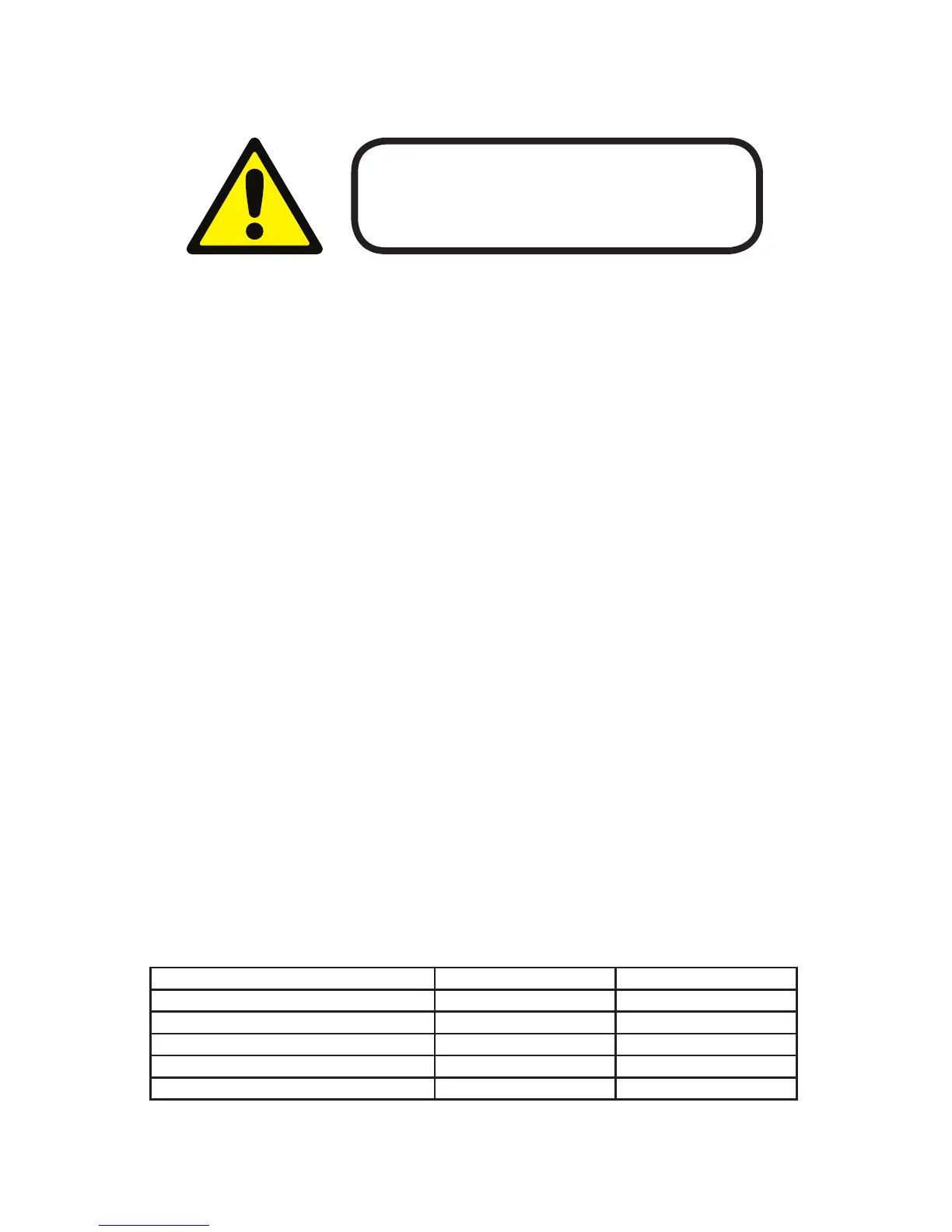
Before replacing a fuse, disconnect the power cord.
ALWAYS replace with the same type and rating of fuse.
3. SETUP