JUST POWER ON58
Step 1: It is recommended to use a 2.5mm
2
outdoor power cable. Disconnect the
cable connector from the EP760 positive and negative connectors. (You’re strongly
recommend to distinguish the positive and negative connectors with different colors.)
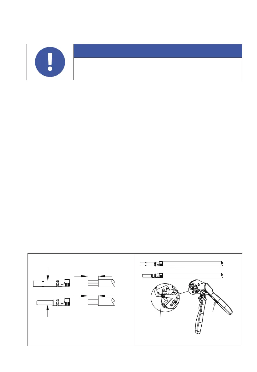
Step 2: Use wire strippers to peel off the insulation layer of the positive and negative
power cables. For the specific stripping length, refer to Figure 6-12-1.
Step 3: Insert the positive and negative power cables into the positive and negative
metal terminals separately. Crimp them tightly to ensure that the cable can not be
pulled out. See Figure 6-12-2.
Step 4: Insert the crimped positive and negative power cables through the locking
nut and into the corresponding plastic housing until you hear a click, which
indicates that the metal core has been snapped into place, and then tighten the
locking nut. See Figure 6-12-3 and 6-12-4.
Step 5: Use a multimeter to confirm the positive and negative poles. See Figure 6-12-5.
Confirm that the voltage is within 150V-500V.
The positive and negative connectors can then be inserted into the PV input of
EP760 inverter. See Figure 6-12-6.
If you need to remove the PV positive and negative connectors from the inverter,
use a removal crimper to insert the bayonet as shown in Figure 6-12-7, and press
down to remove the connectors.
6.6.6. Connect PV Cables
Attention
Before removing the PV input positive and negative connectors,
make sure the DC switch on the EP760 inverter has been set to “OFF”.
Figure 6-12-1 Figure 6-12-2
1. Positive metal core
2. Negative metal core
7-9mm
7-9mm
2
1
Crimper
Press