Omega Operating Manual BMG LABTECH
22/29 0415B0001G 2014-05-16
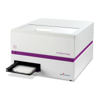
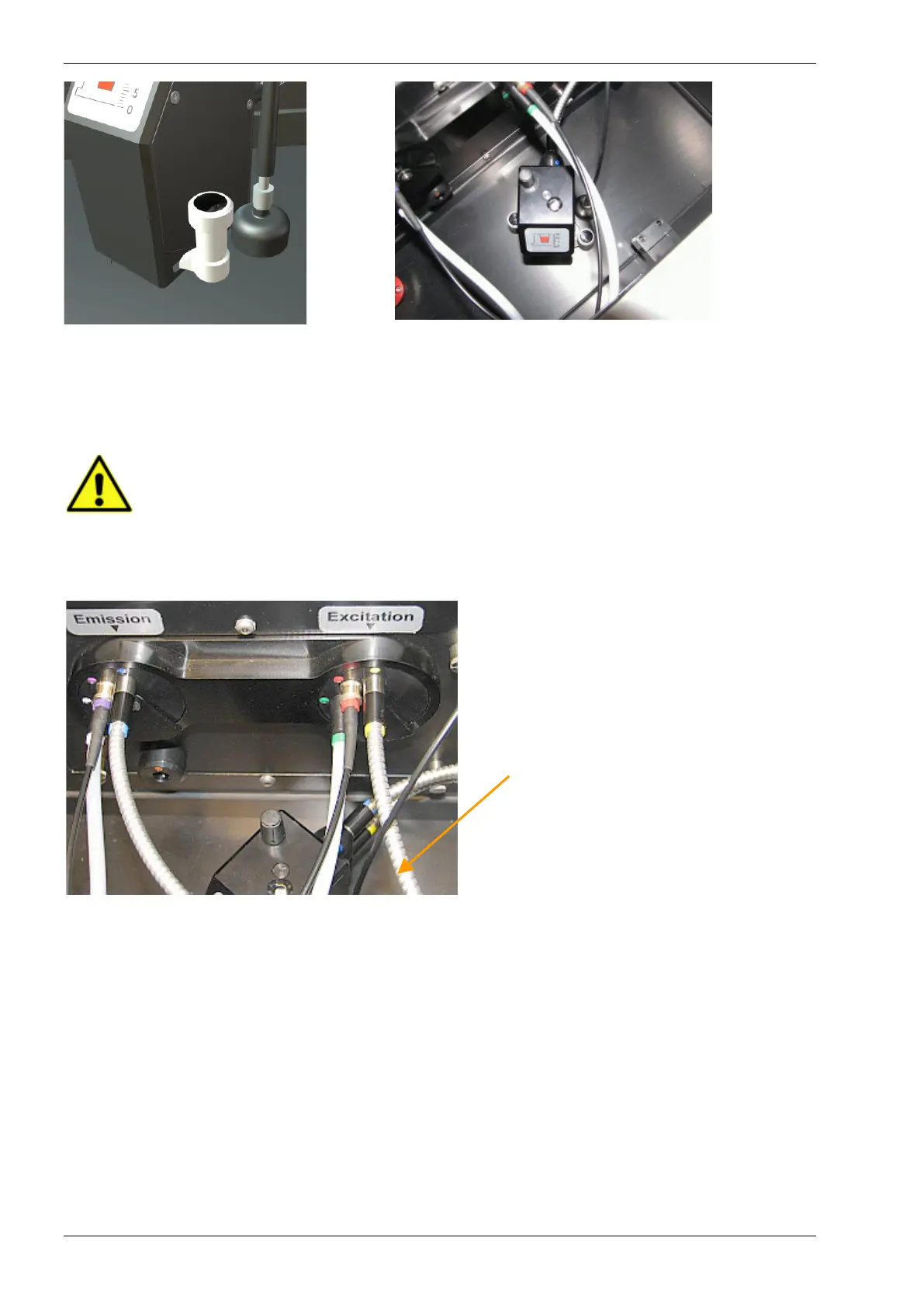
Figure 22: Schematic of the Quick-Fix holder (left) and actual image of the TRF-optic head in the
instrument (right).
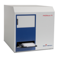
Connect the excitation light guide (yellow) to the matching pin hole (yellow) of the Excitation Positioning
Wheel.
Be careful NOT TO OBSTRUCT the black light guide of the absorbance spectrometer. The
excitation light guide of the TRF optic head must reside BELOW the black light guide of
the absorbance spectrometer (Fig. 23)
Connect the emission light guide (blue) to the matching pin hole (blue) of the Emission Positioning Wheel.
Note: The excitation light guide must be
positioned BELOW the black thin light guide of
the absorbance spectrometer.
Figure 23: Final look of the installed
TRF optic head and light guides.