7. To install the on-board monitor wiring harness and on-board monitor
EN/15
Retrofit/Installation kit No. 65 90 0 025 169 Issue date: 10.2001
Installation instructions No. 01 29 0 030 090
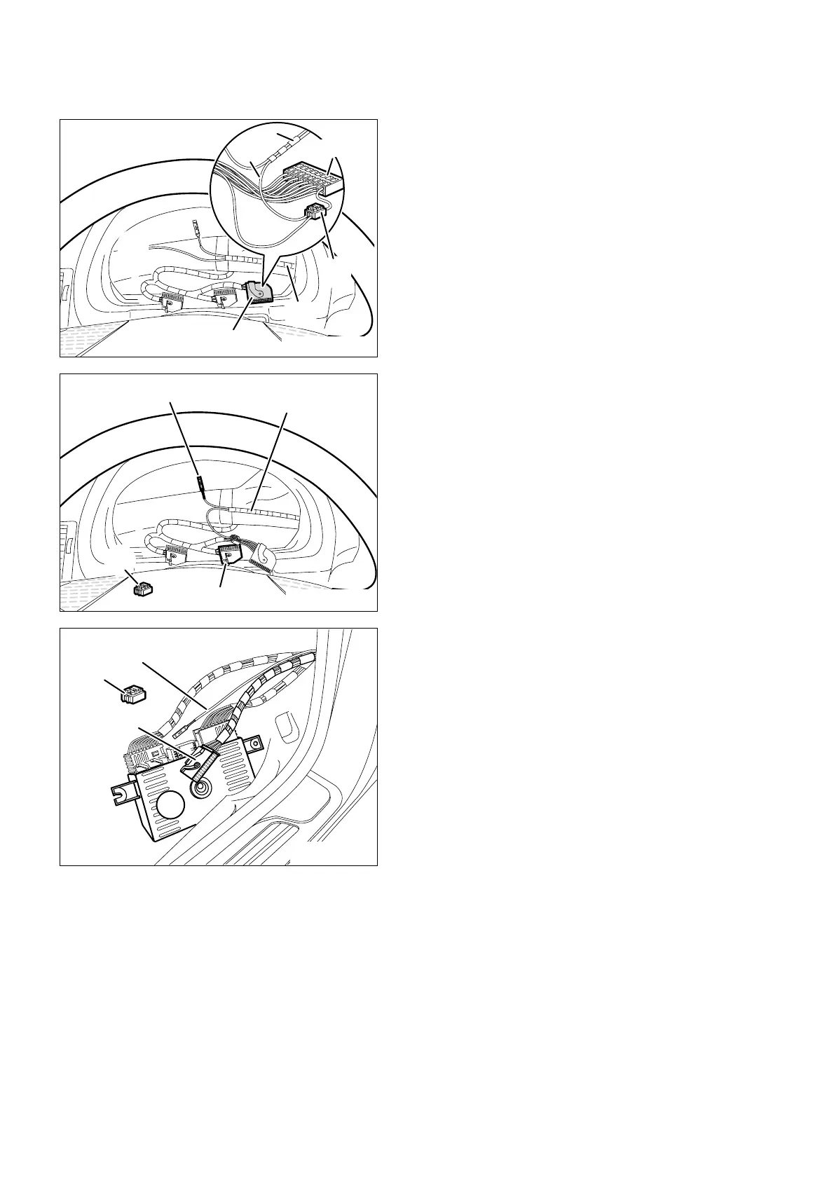
Pin branch cable A6, socket contact, cable
colour black/white, of the on-board monitor
wiring harness A into the free plug-in place PIN3
of the connector X10113.
If PIN3 at the connector X10113 is assigned, cut
off socket contact of branch cable A6 and using
a 2-way insulation-piercing connector (10)
connect to tacho A signal, cable colour
black/white, PIN3, of the connector X10113.
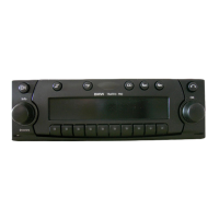
Connect branch A5, free cable end, brown/red
cable, on the on-board monitor wiring harness A,
to the DFAHL signal, brown/red cable, PIN1 on
the connection plug X10114 using a double
insulation-piercing connector (10).
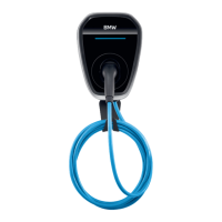
Dismantle light module (40), unplug the black 54-
pole socket housing X10117 from the light
module (40) and open it.
Pin branch cable A4, socket contact, cable
colour blue/yellow, of the on-board monitor
wiring harness, into the free plug-in place PIN38
of the socket housing X10117.
If PIN38 at the socket housing X10117 is
assigned, cut off socket contact of branch cable
A4 and using 2-way insulation-piercing
connector (10) connect to RS signal, cable
colour blue/yellow, PIN38 of the socket housing
X10117.
Then close socket housing X10117, connect it
and re-install light module (40).
If necessary, bind back excess length of branch
cable A4.