15
2.2.4 - FORZA RISULTANTE
SULL’ALBERO
Organi di trasmissione calettati sugli alberi
di ingresso e/o di uscita del riduttore ge-
nerano forze la cui risultante agisce in
senso radiale sull’albero stesso.
L’entità di questi carichi deve essere
compatibile con la capacità di sopporta-
zione del sistema albero-cuscinetti del
riduttore, in particolare il valore assoluto
del carico applicato (R
c1
per albero di in-
gresso, R
c2
per albero di uscita) deve
essere inferiore al valore nominale (R
x1
per albero di ingresso, R
x2
per albero di
uscita) riportato nelle tabelle dati tecnici.
Il procedimento descritto si applica indiffe-
rentemente all’albero veloce o all’albero
lento avendo l’avvertenza di utilizzare i co-
efficienti K
1
o K
2
, in funzione dell’albero
interessato alla verifica.
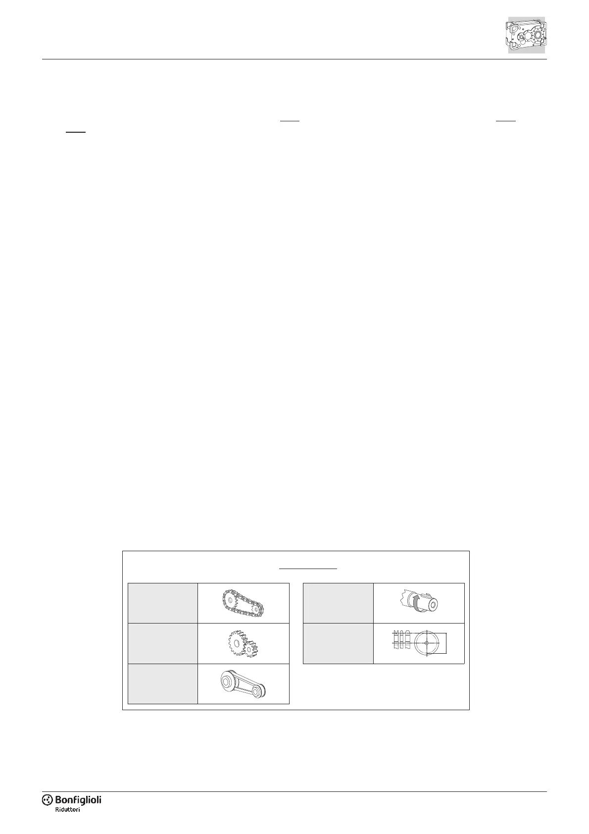
Il carico generato da una trasmissione
esterna può essere calcolato, con buona
approssimazione, tramite la formula se-
guente:
2.2.4 - CALCULATING THE
RESULTING OVERHUNG
LOAD
External transmissions keyed onto input
and/or output shaft generate loads that
act radially onto same shaft.
Resulting shaft loading must be compat-
ible with both the bearing and the shaft
capacity.
Namely shaft loading (R
c1
for input shaft,
R
c2
for output shaft), must be equal or
lower than admissible overhung load ca-
pacity for shaft under study (R
x1
for input
shaft, R
x2
for output shaft). OHL capabil-
ity listed in the rating chart section.
The procedure described above applies
to both the input shaft and the output
shaft, but care must be taken to apply
factor K
1
or factor K
2
to suit the particu-
lar shaft.
The load generated by an external
transmission can be calculated, to a
good approximation, by the following
equation:
2.2.4 - AUF DIE WELLE WIRKENDE
KRAFT
Externe Vorgelege auf den Antriebs-
und/oder Abtriebswellen des Getriebes
entwickeln Kräfte, die radial auf die Welle
einwirken. Die resultierende Wellenbela-
stung muss mit der Widerstandskraft des
Systems Welle/Lager des Getriebes kom-
patibel sein; vor allem muss der Absolut-
wert der ausgeübten Kraft (R
c1
für An-
triebswelle, R
c2
für Abtriebswelle) unter
dem in der Tabelle mit den technischen
Daten angegebenen Nennwert (R
x1
für
Antriebswelle, R
x2
für Abtriebswelle) lie-
gen.
Die beschriebene Vorgehensweise gilt
ohne Unterschied für die Antriebs- und
für die Abtriebswelle, wobei entsprechend
der jeweils betroffenen Welle die Koeffi-
zienten K
1
oder K
2
verwendet werden
müssen.
Die von einer äußeren Übertragung ausge-
übte Kraft kann mit gutem Näherungswert
mit folgender Formel berechnet werden:
R
2000 M K
d
c
r
=
´´
K
r
=1 M [Nm]
K
r
= 1.25 d [mm]
K
r
= 1.5 - 2.0
M
d
2.2.3 - DISPOSITIVO ANTI-RITORNO
Se il riduttore è specificato con dispositi
-
vo anti-ritorno, verificare la capacità di
carico di quest’ultimo nella relativa se
-
zione 3.6.3
di questo catalogo e assicu
-
rarsi che il valore di coppia massima
M
1MAX
non sia mai trasmesso al riduttore
durante il suo funzionamento.
2.2.3 - BACKSTOP DEVICE
If the gear unit is specified with a back
-
stop, verify the load capacity of the de
-
vice at section 3.6.3
of this catalogue
and make sure the torque M
1MAX
is
never exceeded in operation.
2.2.3 - RÜCKLAUFSPERRE
Wird das Getriebe mit Rücklaufsperre
bestellt, muss deren Belastbarkeit im
entsprechenden Abschnitt 3.6.3
dieses
Katalogs überprüft werden; zudem ist si
-
cherzustellen, dass der Wert des maxi
-
malen Drehmoments M
1MAX
während
des Betriebs niemals auf das Getriebe
übertragen wird.
 Loading...