173
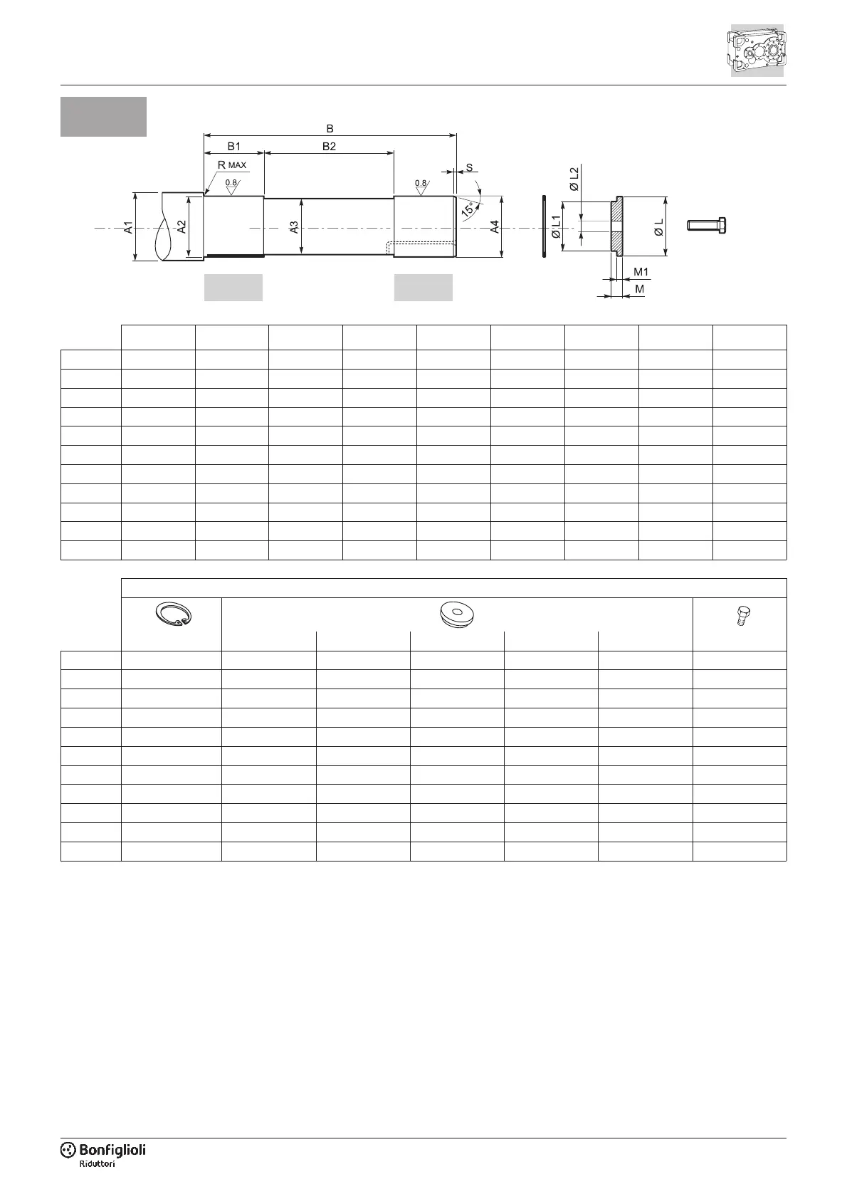
A1 A2 A3 A4 B B1 B2 R S
HDP 60
³ 90 72 h7 69 70 g6 328 59 194 2.5 2.5
HDP 70
³ 104 82 h7 79 80 g6 332 77 174 2.5 2.5
HDP 80
³ 119 97 h7 94 95 g6 398 95 205 2.5 2.5
HDP 90
³ 136 112 h7 109 110 g6 440 87 273 2.5 2.5
HDP 100
³ 138 125 h6 119.5 120 g6 517 104 328 3 2.5
HDP 110
³ 148 135 h6 129.5 130 g6 523 104 334 3 2.5
HDP 120
³ 158 145 h6 139.5 140 g6 550 104 354 3 2.5
HDP 130
³ 188 175 h6 169.5 170 g6 681 104 462 3 2.5
HDP 140
³ 198 185 h6 179.5 180 g6 689 104 470 3 2.5
HDP 150
³ 228 215 h6 209.5 210 g6 839 104 593 3 3
HDP 160
³ 228 215 h6 209.5 210 g6 839 104 593 3 3
Escluso dalla fornitura / out of scope for supply / Nicht im Lieferumfang enthalten
UNI7437 UNI5739
LL1L2MM1
HDP 60
— 90 70 d9 22 10 8.5 M20x50
HDP 70
— 100 80 d9 22 10 8.5 M20x50
HDP 80
— 115 95 d9 26 15 13.5 M24x60
HDP 90
— 130 110 d9 26 15 13.5 M24x60
HDP 100
120x4 120 d9 96 26 16 12 M24x65
HDP 110
130x4 130 d9 105 26 16 12 M24x65
HDP 120
140x4 140 d9 115 26 19 15 M24x70
HDP 130
170x4 170 d9 142 33 21 17 M30x80
HDP 140
180x4 180 d9 150 33 21 17 M30x80
HDP 150
210x5 210 d9 178 33 29 18 M30x90
HDP 160
210x5 210 d9 178 33 29 18 M30x90
S
1 2
Per agevolare le operazioni di smontag-
gio è consigliabile realizzare il perno
macchina dotato di un foro adatto al
passaggio di una sostanza antiruggine
(2) e/o predisposto per il montaggio di
una boccola cilindrica autolubrificante
nel tratto cilindrico di guida opposto al
calettatore (1).
In presenza di carichi assiali esterni, vi
-
brazioni, problemi di sicurezza, richiesta
di elevata affidabilità o posizioni di mon
-
taggio sfavorevoli (es. V5, albero lento
verso il basso) è necessario prevedere
opportuni dispositivi atti a fissare assial
-
mente l’albero ed ad impedirne lo smon
-
taggio accidentale.
To facilitate part removal in the area of
the cylindrical guide opposite the shrink
disc, install a machine pivot to which a
self-lubricating cylindrical bushing (1)
can be fitted and/or with a hole big
enough to allow application of a rust
treatment (2).
In the presence of external thrust loads,
vibration, safety problems, requirements
for enhanced reliability, or unfavourable
mounting positions (e.g. V5 mounting
positions, output shaft directed down
-
wards), install suitable devices to secure
the shaft in an axial direction and pre
-
vent accidental decoupling.
Um den Ausbau aus der Zylinderführung
an der Schrumpfscheibe zu erleichtern,
wird empfohlen, den für die Montage be-
stimmten Maschinenzapfen mit einer
selbstschmierenden Zylinderbuchse (1)
und/oder mit einer Öffnung zum Einbrin
-
gen von Rostschutzmittel (2) zu versehen.
Beim Vorhandensein von externen Axial
-
kräften, Vibrationen, Sicherheitsproblemen,
Auflagen für höhere Zuverlässigkeit oder
ungünstigen Montagepositionen (z.B. V5,
nach unten gerichtete Abtriebswelle) sind
geeignete Vorrichtungen vorzusehen, die
die axiale Befestigung der Welle gewährlei
-
sten und dessen unvorhergesehene Ablö
-
sung verhindern.
 Loading...