19
3. Carichi radiali e assiali albero
veloce
Per vericare la sopportazione ra-
diale riferirsi allo schema illustrato al
paragrafo 2.2.5 e confrontare la forza
radiale Rc gravante sull’albero con il
carico ammissibile Rx corrispondente
alla distanza di applicazione della for-
za stessa dalla mezzeria dell’albero.
Il carico ammissibile Rx
1
per l’albero
veloce si ricava moltiplicando il valore
nominale Rn
1
, reperibile nelle tabelle
dati tecnici, per il coefciente di spo-
stamento K
1
.
I carichi radiali nominali Rn sono re-
lativi alle condizioni di calcolo più sfa-
vorevoli in quanto a verso di rotazione
e angolo di applicazione della forza, e
rappresentano pertanto un valore con-
servativo.
Per un calcolo puntuale, o in caso di
HDP 4 stadi con albero bisporgente
(LD, RD e DD), consultare il Servizio
Tecnico di Bonglioli Riduttori. Con-
giuntamente al carico radiale è applica-
bile un carico assiale An
1
≤ 0.2 x Rn
1
.
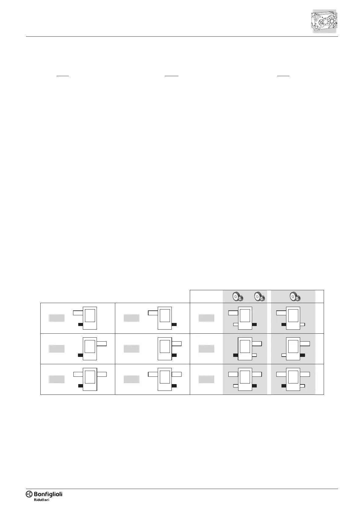
Per le esecuzioni con albero bispor-
gente il carico radiale ammissibile è
riferito all’estremità evidenziata in nero
nello schema seguente:
Per carichi radiali agenti su entrambe le
sporgenze d’albero consultare il Servizio
Tecnico di Bonglioli Riduttori.
3. Overhung and thrust loads
on input shaft
When checking the overhung load
capacity refer to scheme shown at
paragraph 2.2.5. Calculate the admis-
sible overhung load Rx that is relevant
to the distance the force applies from
shaft midpoint and compare this with
the force Rc that acts onto the shaft.
Multiply the nominal radial load Rn
1
,
as listed in the technical data section,
for the load location factor K
1
to get
the permissible overhung load Rx
1
for
the output shaft.
Rated overhung loads Rn are calcu-
lated for the most unfavourable condi-
tion as far as direction of rotation and
the angle the force applies onto the
shaft. Catalogue values are therefore
conservative, for an in-depth calcula-
tion, or in case of HDP with 4 reduc-
tions and through-shafts (LD, RD and
DD), contact the Technical Service of
Bonglioli Riduttori.
When a radial force applies a thrust
load An
1
≤ 0.2 x Rn
1
is also permitted.
In the case of gearboxes with through-
shafts the maximum permitted over-
hung load refers to the shaft end high-
lighted in black below:
If an overhung load is applied to both
shaft ends, contact Bonglioli Riduttori’s
Technical Service for advise.
Wirken auf beide Wellenzapfen Radialkräf-
te wenden Sie sich bitte an den technischen
Kundendienst von Bonglioli Riduttori.
3. Radial- und Axialkräfte auf
der Antriebswelle
Um die zulässige radiale Belastung zu
überprüfen, beziehen Sie sich auf das
in Abschnitt 2.2.5 dargestellte Sche-
ma. Berechnen Sie die zulässige Radi-
allast Rx in Abhängigkeit vom Abstand
zum Mittelpunkt der Welle und ver-
gleichen Sie diese mit der Radialkraft
Rc. Die zulässige Last Rx
1
für die An-
triebswelle wird errechnet, indem der
Nennwert Rn
1
, der den Tabellen mit
den technischen Daten entnommen
werden kann, mit dem Verschiebungs-
koefzienten K
1
multipliziert wird.
Die Nenn-Radialkräfte Rn beziehen
sich auf die ungünstigsten Berech-
nungsbedingungen hinsichtlich Dreh-
richtung und Anwendungswinkel der
Kraft, und stellen daher einen konser-
vativen Wert dar.
Für eine spezische Berechnung, oder
im Falle von HDP mit 4 Getriebestufen
und zwei Wellenstummeln (LD, RD
und DD), siehe unseren Technischen
Service.
Zusammen mit der Radialkraft ist eine
Axialkraft von An
1
≤ 0.2 x Rn
1
an-
wendbar. Für die Ausführungen mit
zwei Wellenstummeln bezieht sich die
zulässige Radialkraft auf das im nach-
folgenden Schema schwarz hervorge-
hobene Wellenende:
4x2x 3x
LDLL LR
RDRL RR
DDDL DR

 Loading...