EN
17
Installation
www.bora.com
4.3 Tools and aids
The following special tools are required to correctly install the
system:
XO
Screwdriver/Torx screwdriver 20
XO
Black, heat-resistant silicone sealant
XO
Fine saw
4.4 Assembly instructions
4.4.1 Safety clearances
XX
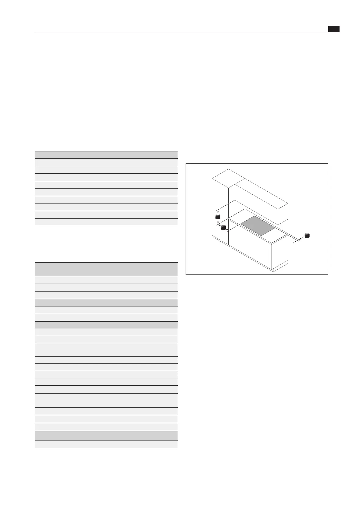
Maintain the following safety clearances:
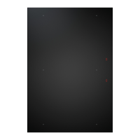
1
3
2
Fig. 4.3 Minimum distance
[1] Minimum clearance of 50mm at the front and back from the
worktop cut-out to the edge of the worktop.
[2] Minimum clearance of 300mm from the left and right of the
worktop cut-out to the adjacent cabinet or wall.
[3] Minimum clearance of 600mm between the worktop and
cabinet above (650 mm in the case of gas devices).
4.4.2 Worktop and kitchen units
XX
Create the worktop cut-out taking into account the specified
cut-out dimensions.
XX
Make sure that the cut surfaces of the worktops are properly
sealed.
XX
Comply with the instructions of the worktop manufacturer.
XO
Cross bars on the kitchen unit in the area of the worktop cut-
out may need to be removed.
XO
No false floor is necessary below the cooktop. If cable
protection (false floor) is planned, the following must be taken
into account:
XO
It must be fitted in such a way that it can be removed for
maintenance work.
XO
To ensure sufficient cooktop ventilation, a minimum
distance of 15 mm to the bottom edge of the cooktop
extractor is to be observed.
XO
The drawers and/or shelves in the floor unit must be removable.
XO
For correct installation, the slide-in units of the base cabinet
must be shortened depending on the installation situation.
4.2 Checking the delivery
XX
Make sure the delivery is complete and check it for damage.
XX
If there are any missing or damaged parts, please notify BORA
After Sales Service.
XX
Do not under any circumstances install parts which are
damaged.
XX
Dispose of transport packaging in the proper manner (see the
Decommissioning, disassembly and disposal chapter).
4.2.1 Scope of delivery of the cooktop
extractor CKA2/CKA2AB
Scope of delivery CKA2/CKA2AB Quantity
Installation instructions 1
Operating instructions 1
Extractor base module (CKA2GM) 1
Air inlet nozzle (CKA2ED/CKAEDAB) 1
Grease filter unit (CKA2FFE) 1
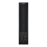
Control unit (CKA2SB) 1
Power supply cable (country-specific) 1
Flexible module (CKA2MF) 1
Ferrite sleeve (UFK) 1
Tab. 4.1 Scope of delivery of the cooktop extractor
4.2.2 Scope of delivery of the cooktops
Scope of delivery CKFI, CKI, CKIW, CKCH, CKCB,
CKG, CKT
Quantity
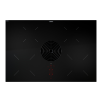
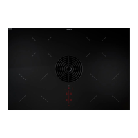
Cooktop 1
Mounting brackets 4
Height adjustment plate set 1
Additional scope of delivery CKFI, CKI, CKIW, CKCH, CKCB
Glass ceramic cleaning instructions 1
Glass ceramic scraper 1
Additional scope of delivery CKG
Cast-iron grate 2
Nozzle set G20/20 mbar natural gas PKGDS2020 1
Flexible gas connection hose, length 500 mm, 1/2”
external thread(EN14800)
1
Cylindrical/conical transition piece 1
Seal 1
Glass ceramic cleaning instructions 1
Glass ceramic scraper 1
Special scope of delivery for Australia and New Zealand:
Gas regulator 1,00 kPa
with test point for natural gas (NG)
1
Test point adapter for liquid gas (LPG) 1
Nozzle set G20/10 mbar (NG/1.0 kPa) – pre installed 1
Nozzle set G31/27,5 mbar (ULPG/2.75 kPa) 1
Additional scope of delivery CKT
Tepan spatula 1
Tab. 4.2 Scopes of delivery of the cooktops
 Loading...