EN
30
Installation
www.bora.com
XO
The connection bracket and connection pieces must be
equipped with a 1/2 inch external thread in accordance with
the regulatory country requirements (see table 4.8).
XX
Connect the appliance as follows:
XX
Switch all appliances off.
XX
Close the gas supply.
XX
Switch off the main switch/automatic circuit breaker before
connecting the cooktop.
XX
Secure the main switch/automatic circuit breaker against
being switched back on without permission.
XX
Make sure the power to the appliance is disconnected.
XX
Check the gas type and gas pressure of the gas supply pipe.
XX
Ensure that the appliance is equipped with the correct nozzle
type in order to guarantee a correct burner flame and safe
operation.
XX
Remove the protective cap from the connection tube.
XX
Use a bayonet socket to connect this directly to the
connection of the gas cooktop using a permitted hose clip to
prevent any leakage of gas.
XO
Only use the connection permitted in your country.
XO
ISO 228-1/ISO7-1(EN10226): cylindrical/conical
XO
ISO 228-1/ISO 228-1: cylindrical/cylindrical
XX
Connect the appliance to the gas supply pipe.
XX
Tighten all connections so that they are secure.
XX
Check that installation has been carried out correctly.
XX
Check the correct functioning of the stopcock.
XX
Check the tightness of the gas connection by conducting a
leak test.
XX
Ensure that there is no risk of ignition sparks.
XX
Do not use fire or an open flame.
XX
Use suitable testing equipment to check all the connections
between the cooktop and the gas connection.
XX
When using a leak spray for this process, ensure that you wet
all connections.
XX
Shut off the gas supply if you determine that gas is escaping
and ventilate the room.
XX
Seal the point from which the gas is leaking.
XX
Re-check all connections and the gas connection.
XX
Repeat the leak test until all connections are tight.
XX
Create a leak test record and give this to the user.
XX
Switch on the main switch/automatic circuit breaker.
XX
Start up the system (see the Operation section)
XX
Check all the functions of the cooktop extractor and cooktop
are working correctly.
XX
Check the burner flame is working correctly, particularly when
the cooktop extractor is in use.
4.14.3 Additional installation notes for
Australia and New Zealand (AU/NZ)
i
Observe the requirements on the installation of the
appliance pursuant to AS/NZS 5601.1: minimum
clearance of the gas burner head from flammable
surfaces.
i
Installation must only be carried out by authorized
personnel.
XX
Please note all previous information in this section.
XX
In addition, adhere to the requirements of the currently
applicable version of the regulations and AS/NZS 5601.1 .
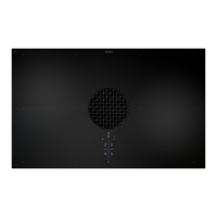
1
L1
2
N PE
220 - 240 V~
Fig. 4.40 Connection diagram 1-phase connection cooktop
Connecting the control unit to the power supply
XX
Connect the mains cable for the control unit to the mains.
XX
Check that installation has been carried out correctly.
XX
Switch on the main switch/automatic circuit breaker.
4.14 Gas installation (only in the case
of gas cooktop CKG)
The gas connection may only be carried out by an authorised
gas fitter in accordance with applicable legal and local
regulations. Comply with local utility company regulations.
Country Regulation/guidelines
Germany DVGW TRGI 2018 and DVGW-worksheet G 600
Austria ÖVGW-GK guidelines
Switzerland SVGW Gas Regulations G1
EKAA guideline 6517
Regulations of the Vereinigung Kantonaler
Feuerversicherungen (VKF)
Netherlands
Belgium
France
Regulations of standard NBN D 51-003
Regulations and connection requirements of the
gas supply company (G.D.F.) and electricity supply
company (E.D.F)
Tab. 4.8 Country requirements (information supplied without
liability)
4.14.1 Ventilation
This appliance is not connected to a flue gas evacuation device.
It must be positioned and connected in accordance with the
applicable installation conditions. Suitable ventilation measures
must be adhered to in particular.
XX
Always ensure sufficient ventilation during operation (of the
appliance).
4.14.2 Gas connection
This gas cooking appliance corresponds to device class 3. It is
equipped with a flexible connection tube. The gas hose must
meet the requirements of EN14800.
XO
The installation of a gas bayonet socket in the adjacent unit is
recommended.
XO
The connection of liquid gas (LPG) is performed with the
interconnection of a sealed connection socket (pipe D: 8 x
1 mm).
XO
The connection to the gas supply is to be created with flexible
and seamless pipes made from stainless steel.
XO
The connection with a bayonet hose is to be created in
accordance with DIN 3383 with a maximum length of
1500mm.
 Loading...