EN
28
Installation
www.bora.com
[M] Fan 2
[S1] External switch contact
4.13.1 Establishing contact between the
cooktop extractor and cooktops
XX
Only use the cables supplied in the scope of delivery.
45
1 2 3
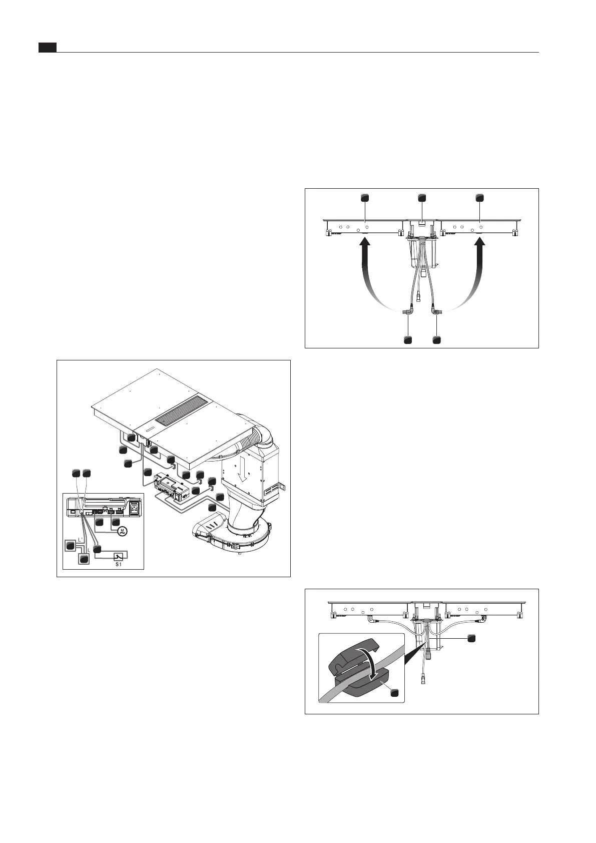
Fig. 4.35 Connecting the control cables to the cooktops
[1] Left cooktop
[2] Cooktop extractor
[3] Right cooktop
[4] Right cooktop control cable (R)
[5] Left cooktop control cable (L)
XX
Connect the cooktop extractor control cables to the adjacent
cooktops.
XX
Ensure that each cable is connected to the correct socket.
XO
The right angle connectors of the control cables are labelled L
(left) and R (right).
4.13.2 Fitting split ferrite sleeves
i
The cooktop extractor connection cable must be filtered
with a ferrite sleeve for reasons of electromagnetic
compatibility.
1
2
Fig. 4.36 Fitting split ferrite sleeves
[1] Connection cable
[2] Split ferrite sleeve
XX
Fit the split ferrite sleeve [2] provided in the scope of delivery
to the connection cable [1].
XX
Check the correct installation, as well as the firm positioning
of the connection cables.
XX
Close and secure the control unit cover.
XX
Screw down the lid with the screw provided (max. 2 Nm).
XX
Make sure that the cable is not damaged or trapped.
4.13 Establishing communication and
power connection
i
The cooktops of the BORA Classic 2.0 system can only be
operated with the central operating unit of the cooktop
extractor CKA2/CKA2AB.
i
The communication link between the cooktop extractor
and cooktops is established via the control lines of the
central operating unit.
i
The cooktops have their own electricity supply. This must
be connected during installation.
i
The central operating unit is supplied with electricity by
the communication cable.
11 10
15
16
14
1
5
4
4
2
2
1
3
7
8
9
6
1312
Fig. 4.34 Connection diagram for cooktop extractor CKA2/
CKA2AB
[1] Cooktop mains cable
[2] Power supply per cooktop
[3] CAT 5e communication cable
[4] CAT 5e cooktop communication cable
[5] USB interface
[6] Control unit mains cable (country-specific)
[7] Control unit power supply
[8] Fan 1 mains cable
[9] Fan 1 control cable
[10] Fan 2 mains cable
[11] Fan 2 control cable
[12] Home Out connection
[13] Home In connection
[14] Home In connection cable
[15] External device
[16] Power supply cable for external device
 Loading...