EN
27
Installation
www.bora.com
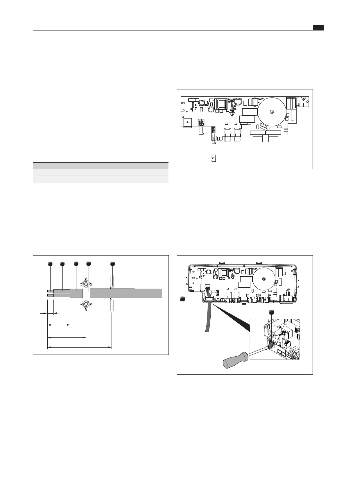
Installing the external switch device
Depending on the type of switch device, connect the connection
cables to either the Home In or the Home Out connection clamp.
XX
Adhere to the connection diagram when connecting Home In
and Home Out.
Home
In
Home
Out
X 311.1
X 311.2
X 312.1
X 312.2
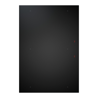
Fig. 4.32 Connection diagram for the external switch contacts
XX
Connect the cable for the relevant contact to the switch
contact clamp in accordance with the connection diagram.
XO
In order to connect the Home In interface, the installed bridge
must be removed.
i
The Home In contact must be bridged if this is not used
(bridged on delivery).
i
For connections to the Home In connection clamp, no
ferrules may be used.
1
2
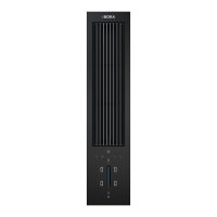
Fig. 4.33 Home Out contacts with strain relief
[1] Strain relief clamp
[2] Snap-out element for cable feed
XX
Clamp the connection cable in the strain relief clamp [1] in
accordance with the wire cross section used.
XX
Remove the snap-out element [2] required for the cable feed
from the plastic housing of the control unit.
i
If external switching devices are connected both to the
Home In and Home Out interfaces, both cables should be
secured with the strain relief clamp.
XX
Ensure that the control unit is disconnected from the power
supply.
XX
Loosen the screw [4] on the housing cover [1].
XX
Carefully release all locks [2] with a slotted screw driver.
XX
Remove the housing cover [1] from the housing subshell [3] by
lifting it up.
XX
Do not touch the electronic unit [5].
i
The electronic unit can contain residual charge. You must
therefore be careful not to touch the exposed contacts on
the electronic unit.
Preparing connection cables for external switching
equipment
Use connection cables of the following types and manufacturers
to connect external switching equipment.
Contact Connection cable
Home In H03VV-F 2x 0.5mm²
Home Out H03VVH2-F 2x 0.75mm²
Tab. 4.6 Connection cable
i
The connection cable is only intended for internal use in
buildings, private households, kitchens or offices!
i
The overall length of the connection cable for external
switching equipment must not exceed 10m!
XX
Prepare the connection cable in accordance with the
prescribed stripping lengths.
5
3
2
1
4
9
25
37
45
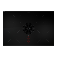
Fig. 4.31 Stripping lengths and installation position of the
connection cable
[1] Stripped wire end
[2] Insulated wire
[3] Jacketed cable
[4] Strain relief clamp
[5] Cable feed snap-out element
XO
Please adhere to the maximum stripping length of the
individual wires of 9 mm on the stripped wire end [1].
XO
Please adhere to the maximum stripping length of the outer
sheath of 25 mm on the insulated wire [2].
 Loading...