EN
23
Installation
www.bora.com
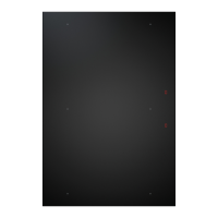
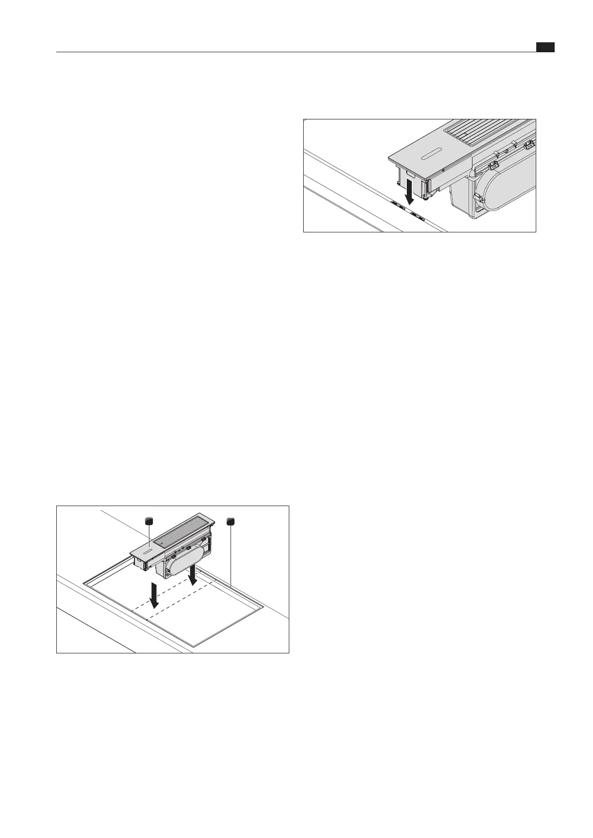
Adjusting the installation height (only in the case
of flush installation)
Fig. 4.21 Height adjustment plates for ush installation
[1] Height adjustment plate
[2] Cooktop extractor
XX
In flush installation, if necessary, lay height adjustment plates
[1] underneath in order to adapt the installation height of the
cooktop extractor [2] to the rebate depth.
4.10 Installing the duct system
i
The duct system must be fitted to the cooktop extractor
free of load and with the power supply switched off.
i
Please bear in mind that for correct installation, the slide-
in units of the base cabinet can be shortened depending
on the installation situation.
XO
The maximum exhaust air duct length with a fan is 6m.
XO
The minimum cross-section of the air ducts must be 176 cm²,
which equates to a round pipe with a diameter of 150 mm or
the BORA Ecotube duct system.
XX
Use only BORA Ecotube duct parts.
XX
Do not use flexible or fabric hoses.
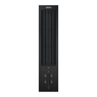
4.10.1 Fitting the duct system to cooktop
extractor CKA2/CKA2AB
i
The floor unit must not be supported on the plinth fan
housing. The plinth fan must be installed free of load and
with the power supply switched off.
i
The plinth fan must only be installed horizontally.
i
Position the plinth fan and control unit in such a way that
they cannot be easily accessed by the user under normal
operating conditions (e.g. behind the plinth panel).
Preparations
XX
Adjust the ducting parts to the height of the worktop.
XX
Saw out the necessary cut-outs for the ducting in the rear
panel of the floor unit.
XX
Depending on the installation situation, adjust the levelling
feet on the floor unit as necessary.
XX
Insert the adapter panel [2] into the connection module [3]
from above.
XX
To do this, slide the adapter panel into the slots on the
connection module [3].
XX
Do not use force to assemble the parts.
XX
Ensure that the lock clicks into place.
Assemble the base module:
XX
Place the base module [1] on top of the connection module
[3] with its adapter panel [2] already fitted.
XX
Do not use excessive force to assemble the parts.
XX
Ensure that the lock clicks into place.
XX
Check that all components are positioned correctly.
XX
Check that the clearance inside the extractor is even.
4.9 Installing the cooktop extractor
i
Clearance of one millimetre should be planned between
the appliances.
i
In the case of flush installation, a clearance of two
millimetres should be planned around the appliances.
XO
Cross bars on the kitchen unit in the area of the worktop cut-
out may need to be removed.
XO
The drawers and/or shelves in the floor unit must be
removable for maintenance and cleaning purposes.
XX
Make sure that the area at the front of the floor unit is
sufficiently ventilated with clean air.
XX
Make sure that the floor unit is not soiled by the ventilation
openings.
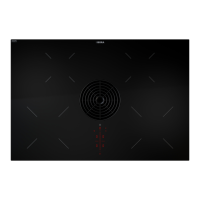
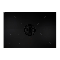
4.9.1 Fitting and positioning the cooktop
extractor
2
Fig. 4.20 Insert the cooktop extractor in the worktop cut-out.
[1] Cooktop extractor
[2] Worktop cut-out
XX
Place the cooktop extractor [1] in the middle of the worktop
cut-out [2].
XX
Position the cooktop extractor [1] with precision.
 Loading...