Do you have a question about the Bosch 15 SEER2 Series and is the answer not in the manual?
Defines warning keywords and symbols used in the document.
Provides crucial safety information and warnings for installation.
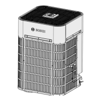
Identifies and illustrates the components of the 3-ton model.
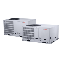
Identifies and illustrates the components of the 5-ton model.
Provides detailed unit dimensions and weight for the 3-ton model.
Illustrates the overall unit dimensions for the 3-ton model.
Shows back and bottom views with dimensions for the 3-ton model.
Shows left and top views with dimensions for the 3-ton model.
Provides detailed unit dimensions and weight for the 5-ton model.
Illustrates the overall unit dimensions for the 5-ton model.
Shows back and bottom views with dimensions for the 5-ton model.
Shows left and top views with dimensions for the 5-ton model.
Checks and preparations required before installing the unit.
Provides instructions and cautions for safely rigging and lifting the unit.
Guidelines for selecting the optimal and safe location for the unit.
Details on connecting the main power supply to the unit.
Instructions and warnings regarding proper unit grounding.
Guidelines for connecting control wiring to the unit.
Illustrates various thermostat wiring configurations for the unit.
Step-by-step guide for initiating the system after installation.
Procedure for charging the system using the weigh-in method.
Method for adjusting refrigerant charge based on subcooling.
Explains the operating logic and compressor speed control.
Lists and describes various sensors and their functions.
Details the defrost cycle initiation and termination.
Explains the function and operation of the crankcase heater.
Describes the operation of the reversing valve in heating/cooling.
Lists and explains various unit protection mechanisms.
Lists error codes and their descriptions for troubleshooting.
Table for checking system parameters and their values.
Diagram and description of the 3-ton outdoor unit control board.
Diagram and description of the 5-ton outdoor unit control board.
Diagram and description of the indoor unit control board.
Troubleshooting steps for low pressure protection errors.
Troubleshooting steps for high compressor discharge temp.
Troubleshooting steps for temperature sensor faults.
Troubleshooting steps for pressure transducer faults.
Troubleshooting for condenser coil sensor fault.
Troubleshooting steps for DC fan motor faults.
Troubleshooting for EEPROM faults.
Troubleshooting for communication faults in the main control chip.
Troubleshooting steps for high/low voltage protection.
Troubleshooting steps for communication errors.
Troubleshooting steps for IPM module protection.
Troubleshooting for ambient temperature limited conditions.
Safety precautions and notices for cleaning the unit.
Recommended schedule and tasks for regular system maintenance.
| SEER2 | Up to 15 |
|---|---|
| Refrigerant | R-410A |
| EER | Up to 12.5 |
| Cooling Capacity (BTU/h) | 18, 000 - 60, 000 |
| Heating Capacity (BTU/h) | 18, 000 - 60, 000 |
| Sound Level (dB) | 72 |
| Warranty | 10 years |