Installation, Operation, and Maintenance Manual
CA Series Heat Pumps -8733851021 (2025/04) US
| 11
10 Electrical
DANGER
Electric shock!
The system contains an oversize, protective, earthing (grounding) terminal that
must be properly connected, otherwise personal injury or death may result.
WARNING
Personal injury hazard!
Field wiring must be installed by qualified and trained personnel.
WARNING
Personal injury hazard or property damage!
Power to the unit must be within the operating voltage range indicated on the unit's
nameplate or on the performance data sheet.
Personal injury hazard or property damage
NOTICE
!
Properly-sized fusible safety switches or HACR circuit breakers must be installed
for branch circuit protection. See the unit nameplate for maximum fuse or breaker
size.
Product damage
NOTICE
!
Operation of unit on improper line voltage or with excessive phase imbalance will
be hazardous to the unit, constitutes abuse and may void the warranty.
Product damage
NOTICE
!
All high-voltage connections must be torqued as specified by the component's
manufacturer.
All field-installed wiring must comply with the National Electric Code as well as all
applicable local codes.
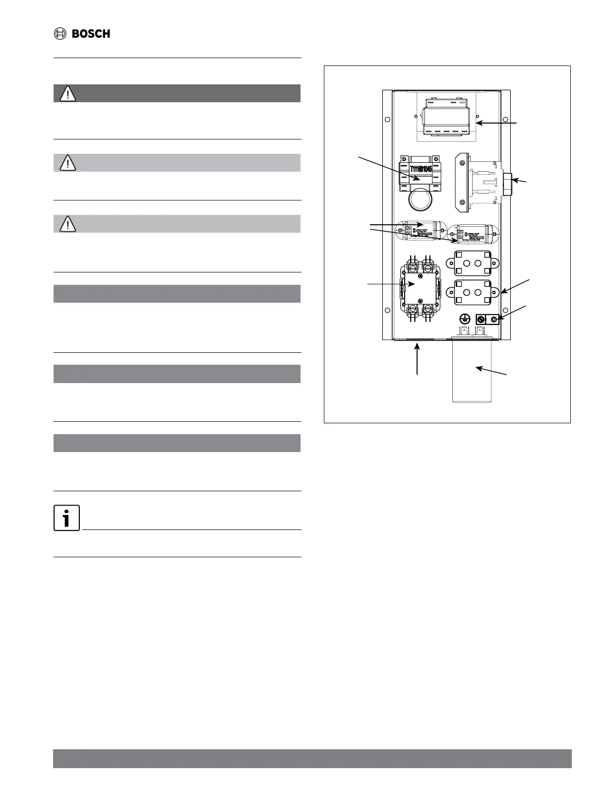
Transformer
Ground lug
Compressor
contactor
Compressor
capacitor
Status switch
(with DDC
option only)
Aux
relay
Line voltage
field access
Disconnect
switch
(optional)
Blower
speed
relays
Figure 3 High Voltage Electrical Box Components Layout
10.1 Electrical High Voltage Wiring
Refer to the unit's electrical data on the unit's nameplate for wire and branch circuit
protection sizing. Supply power voltage and phasing must match the required
voltage and phasing shown on the unit's nameplate.
Route the power-supply wiring through the knockout opening located in the high
voltage electrical box. Refer to Figure 3
Always connect the ground lead to the grounding lug provided in the unit. Follow
the unit's wiring diagram and the following instructions for power leads and ground
connection depending on unit options.
10.1.1 Standard Unit's Power Supply
For standard models, power is connected to the line (L) side of the compressor
contactor and the ground to the ground lug in the unit high voltage electrical box.
10.1.2 Units with Disconnect Switch Power Supply
For models with disconnect switches, connect the field power to the marked
terminals on the disconnect switch, and the ground to the ground lug.