Installation, Operation, and Maintenance Manual
CA Series Heat Pumps - 8733851021 (2025/04) US
14 |
11 Safety Devices and the UPM Controller Overview
CA models are equipped with the Unit Protection Module (UPM) that controls the
compressor operation and monitors the safety.
1
2
3
4
5
6
7
8
9
10
11
12
13
14
15
16
17
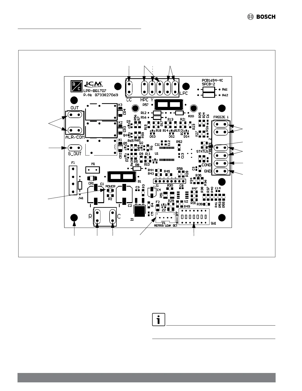
Figure 7 UPM Controller Board
[1] Compressor Contact Output
[2] High-Pressure Switch Connection
[3] Call for Compressor Input Signal (Y1)
[4] Low-Pressure Switch Connection
[5] Water Coil Freeze Connection (FREEZE 1)
[6] UPM Status LED Indicator (Fault Status)
[7] Air Coil Freeze Connection (FREEZE 2)
[8] Condensate Overflow Sensor Connection
[9] Ground
[10] UPM Settings DIP Switch (SW1)
[11] A2L Sensor (field supplied)
[12] 24VAC Power Common
[13] 24VAC Power Input
[14] UPM Standoff
[15] Power LED
[16] Fan (Fan in the event of an A2L leakage)
[17] Dry Contact
When a malfunction light is used for diagnostic purposes, the connection is made at
the dry contact connection terminals of the UPM board.