Installation, Operation, and Maintenance Manual
CA Series Heat Pumps -8733851021 (2025/04) US
| 15
If the thermostat is provided with a malfunction light powered off of the common
(C) side of the transformer, a jumper between “R” and “COM” terminal of “ALR”
contacts must be installed.
Each unit is factory equipped with a UPM that controls the compressor operation
and monitors the safety controls that protect the unit.
Safety controls include the following:
• High-pressure switch located in the refrigerant discharge line and wired
across the HPC (High-Pressure Switch Connection) terminals on the UPM.
• Low-pressure switch located in the unit refrigerant suction line and wired
across the LPC (Low-Pressure Switch Connection) terminals on the UPM.
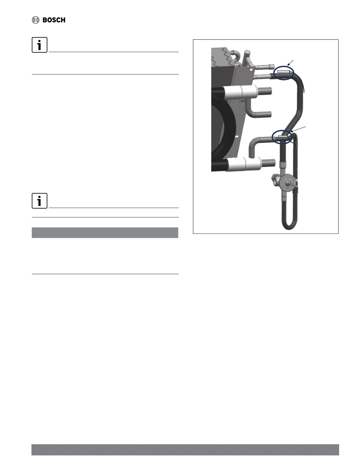
• Waterside freeze protection sensor (FREEZE 1), mounted close
to condensing water coil (Refer to Figure 8), monitors refrigerant
temperature between condensing water coil and thermal expansion valve.
If temperature drops below or remains at freeze limit trip for 120 seconds,
the controller will shut down the compressor and enter into a soft-lockout
condition. The default freeze limit trip is 25°F; however, this can be
changed by flipping DIP switch SW1. (Refer to Figure 7, item [10].)(Refer
to Figure 9.)
The UPM Board Dry Contacts are Normally Open (NO).
NOTICE
P
NOTICE
roduct damage!
If the unit is employing a fresh water system (no anti-freeze protection), it is
extremely important to have the Freeze 1 set to 25°F (DIP Switch SW1 set to OFF)
in order to shut down the unit at the appropriate leaving water temperature and
protect your heat pump from freezing if a freeze sensor is included.
• Air coil freeze protection sensor (FREEZE 2), mounted between the
thermal expansion device and the air coil (Refer to Figure 8), monitors
refrigerant temperature between the air coil and thermal expansion valve.
If temperature drops below or remains at the freeze limit trip for 120
seconds, the controller will shut down the compressor and enter into a
soft-lockout condition. The default freeze limit trip is 25°F.
Water
Coil
Freeze
Sensor
Air Coil Freeze
Sensor
Figure 8 Waterside Freeze Protection Sensor (FREEZE 1) and Air Coil Freeze
Sensor Location (FREEZE 2)
Air Coil Freeze Protection Sensor Location (FREEZE 2)
• The condensate overflow protection sensor is located in the drain pan of
the unit and connected to the “COND” terminal on the UPM board. (Refer
to Figure 7, item [8].)



 To Next Page