Safety Devices and the UPM Controller Overview
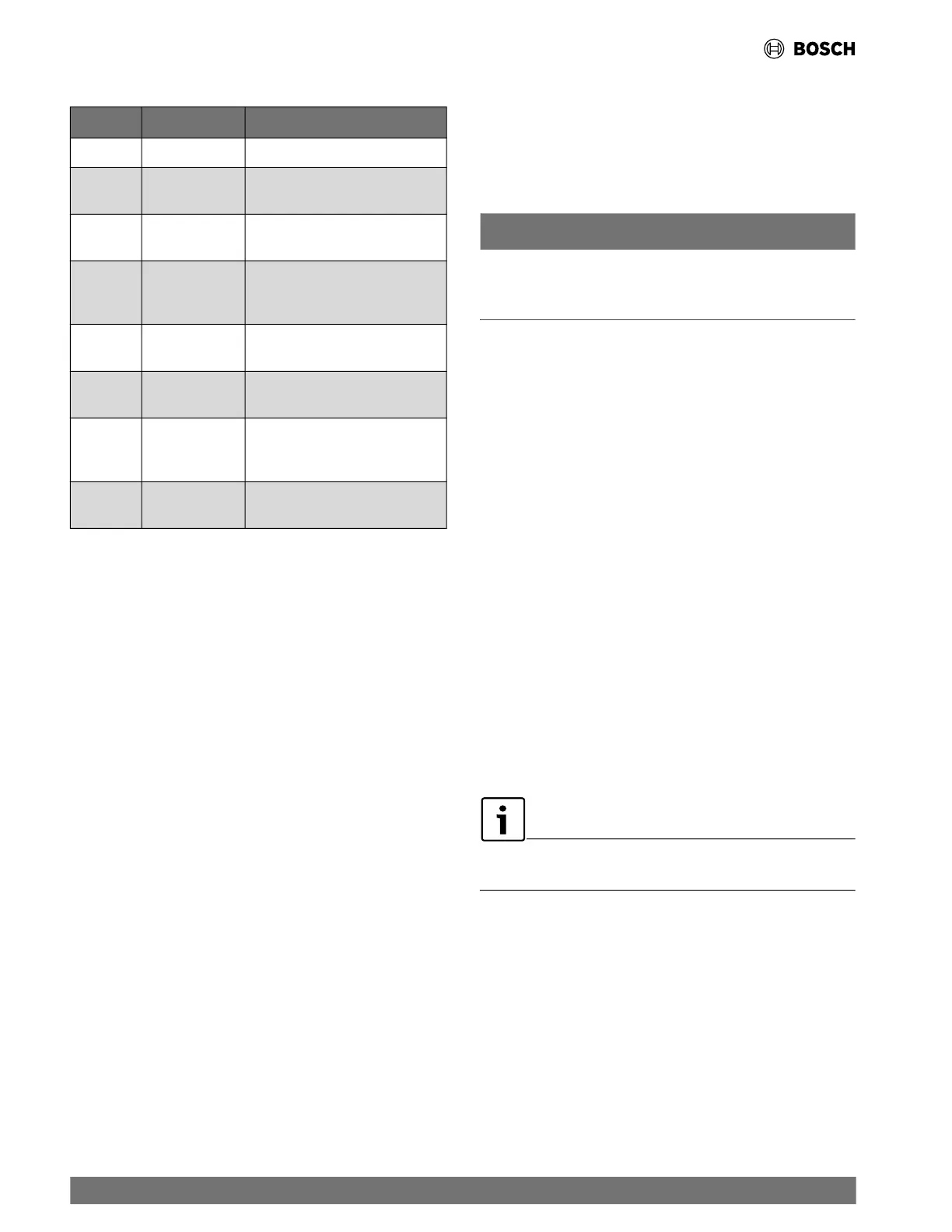
Table 10 UPM Fault Blink Codes
Blinks Fault Fault Criteria
None None All fault conditions normal.
1 High Pressure
Refrigerant discharge pressure has
exceeded 600 PSIG.
2 Low Pressure
Refrigerant suction pressure has
fallen be
low 40 PSIG.
3
Water Coil Freeze
Condition
Refrigerant temperature to the water
coil has fallen below 25°F for 120
seconds.
4
Condensate
Overflow
Co
ndensate levels in the unit drain
pan are too high.
5 Brown Out
Control voltage has fallen
below 18 VAC.
6
Air Coil Freeze
Condition
Refrigerant temperature to the air coil
has falle
n below 25°F for 120
seconds.
7
Refrigerant Leak
Fault
Refrigerant LFL% is more than 15%.
• FREEZE SENSOR: The default setting for the freeze limit
trip is 25°F (FREEZE 1); however, this can be changed to
15°F by flipping the DIP switch position “5” (
Refer to Fig.
18, item [10]) (
Refer to Fig. 21), freeze limit trip should
only be changed to 15°F when a closed loop system with
appropriate antifreeze mixture is used. Since Freeze Sensor
2 is dedicated to monitoring the load side coil, it is
recommended to leave the factory default setting on the
board. The UPM controller will constantly monitor the
refrigerant temperature with the sensor (FREEZE 1)
mounted close to the condensing water coil between the
thermal expansion valve and the water coil. If the
temperature drops below or remains at the freeze-limit trip
for 120 seconds, the controller will shut the compressor
down and enter into a soft-lockout condition. Both the status
LED and the alarm contact will be active. The status LED will
be active, blinking the fault code. The LED will flash (three
times) the code associated with this alarm condition. If this
alarm occurs two times (or four if DIP switch position “1” is
set to “ON”) within an hour, the UPM controller will enter into
a hard-lockout condition. It will constantly monitor the
refrigerant temperature with the sensor (FREEZE 2)
mounted close to the air coil between the thermal expansion
valve and air coil, as shown in Fig. 20. If the temperature
drops below or remains at the freeze limit trip for 120
seconds, the controller will shut the compressor down and
enter into a soft-lockout condition. Both the status LED and
the alarm contact will be active. The status LED will be active,
blinking the fault code. The LED will flash six times the code
associated with this alarm condition. If this alarm occurs two
times (or four times if DIP switch position “1” is set to
“ON”)(
Refer to Fig. 21)(See Table 9) within an hour, the
controller will enter into a hard-lockout condition.
NOTICE
The freeze sensor (FREEZE 1) will not guard against the loss of
water. A flow switch is recommended to prevent the unit from
running if water flow is lost or reduced.
• INTELLIGENT RESET: If a fault condition is initiated,
the five-minute delay on break time period is initiated and the
unit will restart after these delays expire. During this period
the fault LED will indicate the cause of the fault. If the fault
condition still exists or occurs two or four times (depending if
the Lockout DIP switch position “1” is set to “OFF” or “ON”)
(
Refer to Fig. 21)(See Table 9) before 60 minutes, the
unit will go into a hard lockout and requires a manual lockout
reset.
• LOCKOUT RESET: The method to exit a hard lockout
depends of the Reset DIP switch setting:
— To clear a hard lockout when the DIP switch position “2”
is set to “OFF” (Y), power can be cycled OFF then back
ON either at the unit’s thermostat or at the circuit
breaker.
— To clear a hard lockout when the DIP switch position “2”
is set to “ON” (R), power must be cycled OFF then back
ON at the circuit breaker (not at the thermostat).
(
Refer to Fig. 21.) (See Table 9.)
The blower motor will remain active during a lockout
condition.
• PUMP DIP SWITCH: When DIP switch position “7” is set
to “ON” and no Y call has been received in the past 8 hours,
the compressor will have a delay of 30 seconds to allow a
loop pump to circulate water before compressor starts.
(
Refer to Fig. 21.) (See Table 9.)
34 |
CL Series Heat Pumps — 8733838716 (2024/05)

 Loading...