Wiring Diagrams
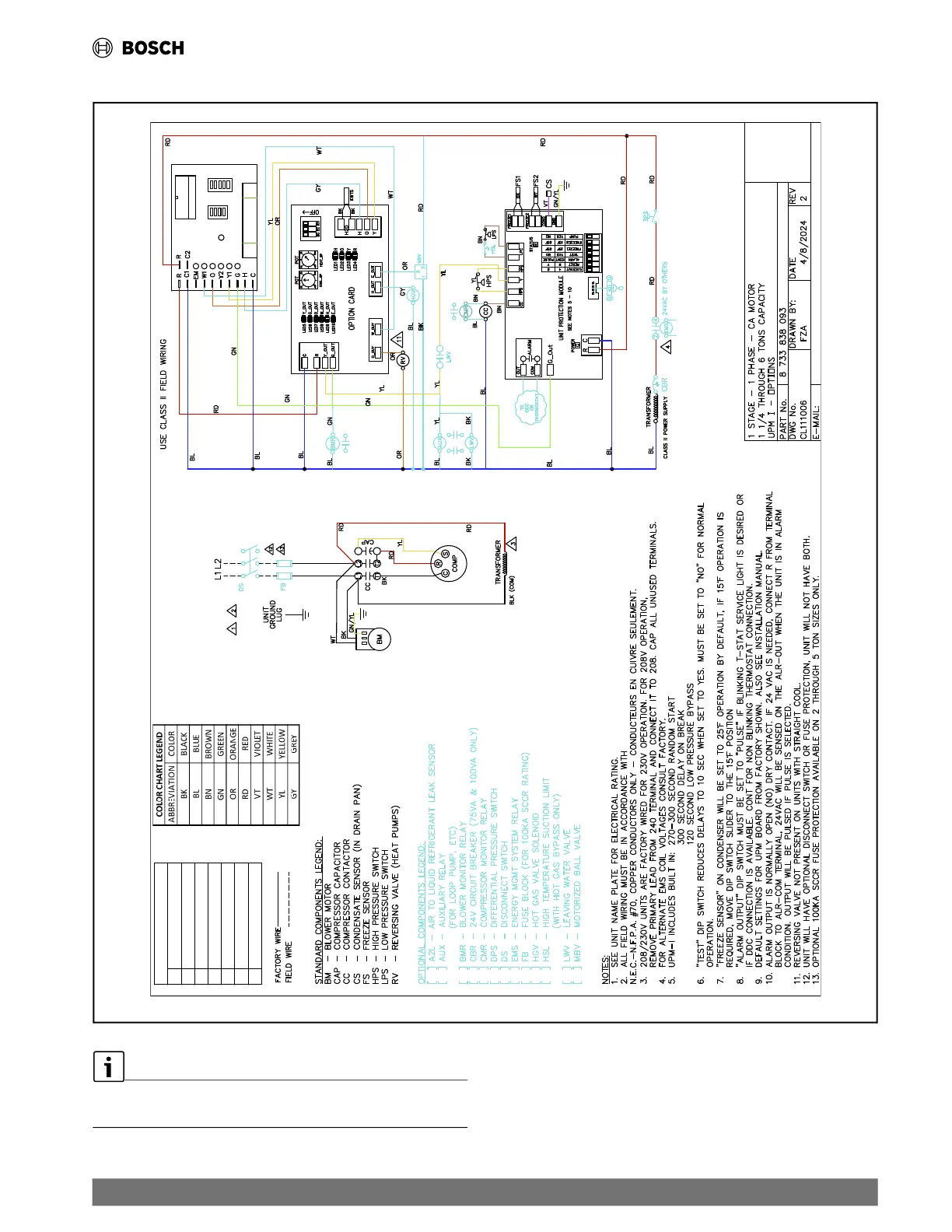
21.6 Single-Stage, Single-Phase Unit with Optional Components and CA Motor
Fig. 34 Single-Stage, Single-Phase Unit with Optional Components and CA Motor
R C G O Y1 Y2 W1 W2 H C
CFM ADJUST
TO ECM MOTOR
A
B
C
D
NORM
(+)
(-)
TEST
YES
HGRH
NO
CFM
UPM STATUS LED - BLINK CODES
1
HIGH PRESSURE FAULT
2
LOW PRESSURE FAULT
3
CONDENSER FREEZE CONDITION
4 CONDENSATE OVERFLOW FAULT
5
BROWN OUT FAULT
6 EVAPORATOR FREEZE CONDITION
7 REFRIGERANT LEAKAGE
FOR REFERENCE ONLY Actual unit wiring may vary from this
example. Always refer to the wiring diagram attached to the unit.
| 77
CL Series Heat Pumps — 8733838716 (2024/05)

 Loading...