23
0° Bevel Stop
To avoid possible injury,
disconnect plug from power
s
ource before performing any assembly,
adjustments or repairs.
NOTE: Your miter saw was completely adjusted at
t
he factory. However, during shipment, slight
misalignment may have occurred. Check the
following settings and adjust if necessary prior to
using this miter saw.
CALIBRATING BLADE AT 0° BEVEL
(90° TO THE TABLE)
Note: Use a 3/8” (10mm) wrench for adjustment.
Note: Calibrating the bevel setting automatically
calibrates the -2° right stop.
1. Lower head assembly and engage head assembly
lock pin.
2. Slide the head assembly completely to the back
and engage the slide rail lock knob by tightening
the knob to the right (clockwise).
3. Pull the bevel lock lever forward to unlock the
head assembly.
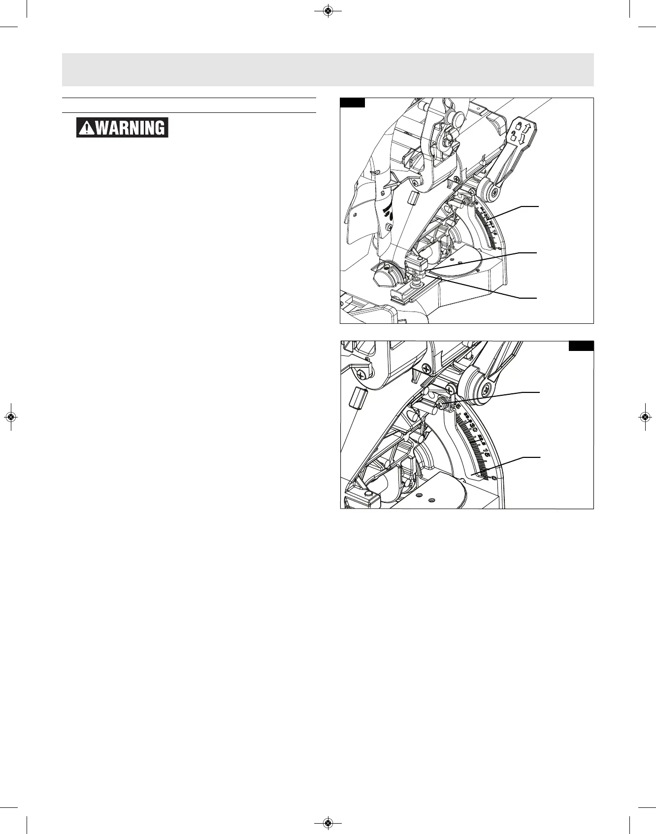
4. Locate the bevel stop bolt below the bevel lock
handle on the right side of the bevel post. This
bolt features a lock nut (see figure 17).
5. Loosen the bevel stop bolt a quarter turn and
then loosen the lock nut. When this is complete
you will be able to adjust the bevel stop bolt by
hand.
A. Rotate the bevel stop bolt clockwise to adjust
the head to the right.
B. Rotate the bevel stop bolt counter-clockwise
to adjust the head to the left.
6. Follow the procedure in “Checking 0° Bevel
Setting” to check your modifications. If further
adjustment is required, repeat the steps above.
7. Once satisfactory, lock the bevel lock at 0° to
prevent movement.
8. Finger tighten the lock nut in place. Once
secured, tighten the lock nut with wrench.
ADJUSTING BEVEL SCALE POINTER
Once you have adjusted the blade to the correct
angle, make sure to adjust the Bevel Scale Pointer.
To do so,
1. Loosen the screw which holds the pointer in
place a quarter turn, (see figure 18).
2. Align the pointer with the 0° line and retighten
screw.
FIG. 17
Bevel Scale
Lock Nut
Bevel Stop
Bolt
Bevel Lock
FIG. 18
Screw
Bevel Scale
Pointer
Adjustments