22
Kerf Insert Adjustment
To avoid possible injury,
disconnect plug from power
s
ource before performing any assembly,
adjustments or repairs.
The kerf inserts should be adjusted close to the
b
lade, but without touching the blade, to avoid
tear-out on the bottom of the workpiece.
1. Hold the saw head assembly down and push in
the head assembly lock pin (item 36 – page 12)
to keep the saw in the DOWN position.
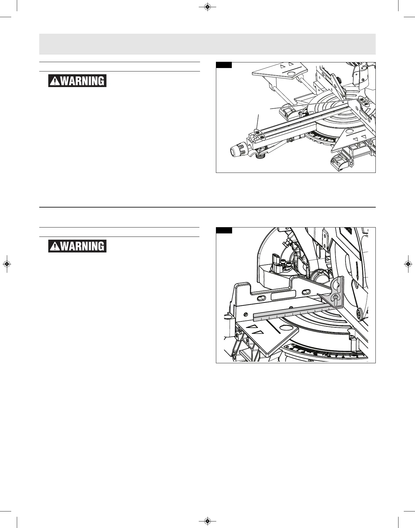
2. Loosen the four kerf screws using a 4mm Hex
key, (figure 15).
3. Adjust the kerf inserts as close to the blade
(teeth) as possible without touching the blade.
4. Tighten the kerf screws.
NOTE: At extreme bevel angles, the saw blade may
slightly cut into kerf insert.
0° Bevel Stop
To avoid possible injury,
disconnect plug from power
source before performing any assembly,
adjustments or repairs.
CHECKING 0° BEVEL STOP SETTING
1. Hold the saw head assembly down and push in
the head assembly lock pin (item 36 – page 12)
to keep the saw in the DOWN position.
2. Slide the head assembly completely to the back
and engage the slide rail lock knob by tightening
the knob to the right (clockwise) (item 25 – page
9).
3. Rotate the table to the 0° miter position.
4. Pull the bevel lock lever forward to unlock the
head assembly.
5. Tilt the saw assembly to the left
(counterclockwise), then rotate to the right
(clockwise) until you feel the stop in the vertical
position. This is where the saw is currently set for
0° bevel cut.
6. Use a combination square to check that the blade
is 90° (square) to the table. Place the square’s
ruler edge against the table and slide it to contact
the blade with the vertical side of the square’s
head (see figure 16).
7. Check that the saw blade’s plate (not teeth) is
touching the square’s 90° side. If the saw blade’s
plate is not in full contact with the square’s body
90° side, follow the “Calibrating Blade at 0º
Bevel” procedures.
FIG. 16
FIG. 15
Kerf
Screws
Adjustments