6 720 809 134 (2013/09)Compress 3000 DW FII
About the appliance | 7
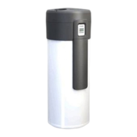
3.6 Appliance layout
Fig. 3 Heat pump
[1] Water inlet - G1"
[2] Internal indirect coil outlet - G1"
1)
[3] Internal indirect coil inlet - G1"
1)
[4] Sensor pocket for temperature sensor (data for solar
system or electric booster heater)
[5] DHW circulation line inlet - G3/4"
[6] Water outlet - G1"
[7] Internal indirect coil
1)
[8] Thermal insulation
[9] Water inlet to condenser
[10] Water outlet from condenser
[11] Fan
[12] Evaporator
[13] Condenser (gas/water heat exchanger)
[14] Compressor
[15] Sensor pocket for DHW temperature sensor
[16] Magnesium anode
[17] Central heating resistor
[18] Adjustable feet (3x)
[19] Air outlet aperture
[20] Air inlet aperture
[21] Condensate outlet
[22] Circulation pump
[23] Front protective covering
[24] Housing ring
[25] Housing lid
[26] Fastening for housing lid
Fig. 4 User interface
[1] Display
[2] Setting buttons
1
2
4
3
6
11 12 13
18
24
25
16
17
3
1
5
23
21
15
22
14
19 20
6
10
9
5
4
7
2
8
6720804054-04.1V
26
1) model HP270-2E1... only
 Loading...

