Appendix
31
Compress Hybrid 7000i AW – 6721833053 (2020/09)
Fig. 42 Hydraulic diagram of a system (1 heating circuit, with bypass and heating pump), with bypass and heating pump; example)
[1] External booster heater
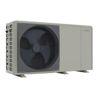
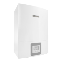
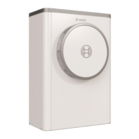
[2] Indoor unit
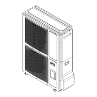
[3] Outdoor unit
[4] Additional heating pump
[5] Bypass (Chapter 4.6, page 8)
Fig. 43 Hydraulic diagram of a system (2 heating circuits, with bypass and heating pump; example)
[1] External booster heater
[2] Indoor unit
[3] Outdoor unit
[4] Additional heating pump (heating circuit 1)
[5] Bypass (Chapter 4.6, page 8)
[6] Heating pump (heating circuit 2)
[7] Mixing valve (heating circuit 2)
1
2
3
4
x=1 - 2 m
x
5
0010036177-001
1
2
3
4
5
6 7
x=1 - 2 m
x
0010036178-001

 Loading...


