10 | Display Configuration
54/148 DDU 9 Bosch Motorsport
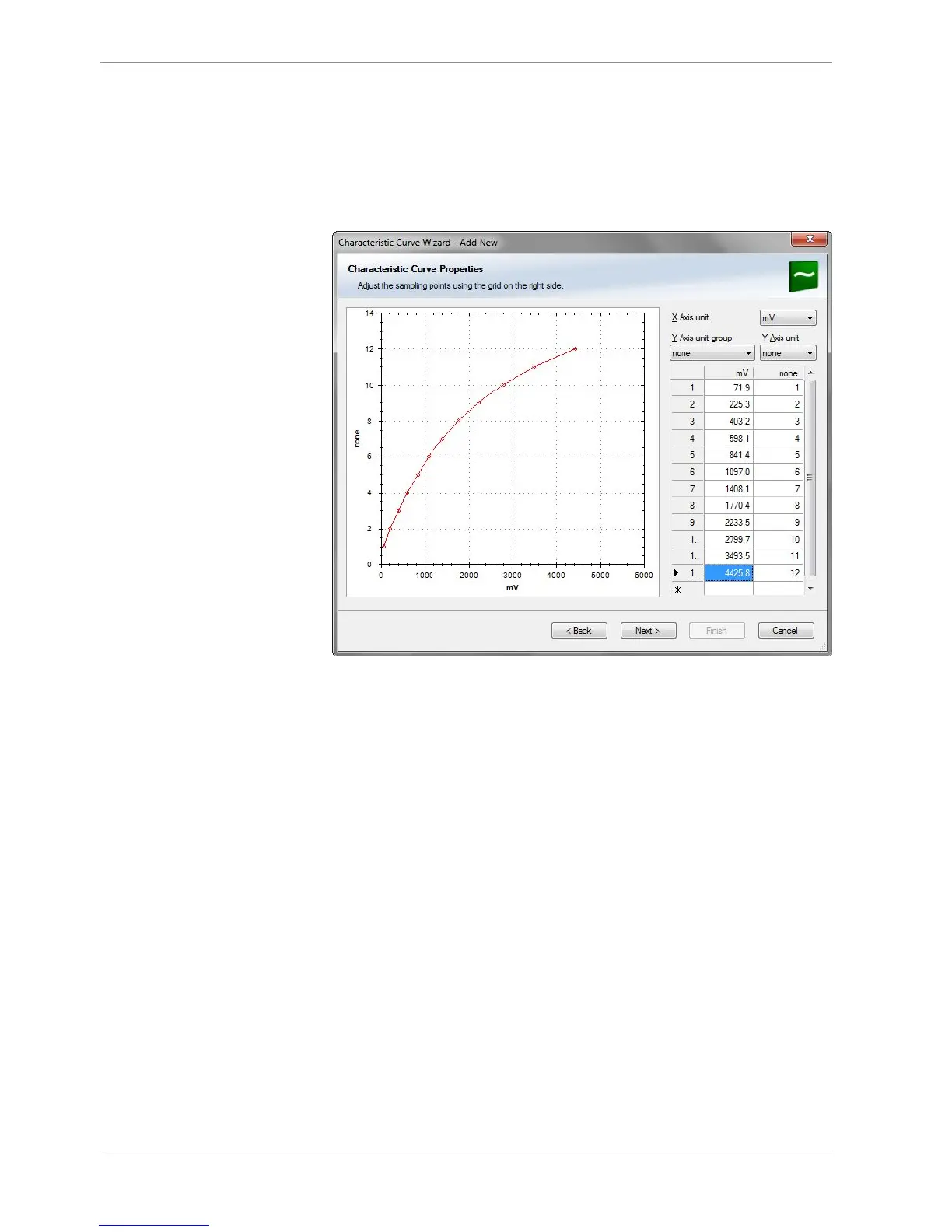
5. Define the relation between voltage and switch position and click on ‘Next’.
Voltage = 5000 x R/(R + 3010)
5000: Sensor supply (mV)
R: Resistor for each Rotary switch position (Ohm)
3010: Pull-up resistor (Ohm)
The following screenshot and the data are an example for a Bosch switch.
6. Define minimum and maximum Limit.
Select “Output data type” from 8, 16 or 32 Bit.
Do not check “Use adjustment value”.
Choose the Measurement sheet and click on ‘Finish’.