English–121 609 929 F69 • (04.10) PS
Standard 0° Angle
So that the standard 0° angle can be easily set again,
the knob 39 engages in the bevel angle range
when the tool arm is swung from the right over the 0°
position.
Full Bevel Angle Range
Place the machine in the working position.
Slide both fence extensions 19 completely outward.
Loosen the clamping handle 14.
Tilt the tool arm with the handle 5 out of the 0° position
somewhat to the left and turn the knob 39 until the de#
sired bevel angle range is indicated.
Swing the tool arm with the handle 5 to the left or right
until the angle indicator 31 or 22 points to the desired
bevel angle.
Hold the tool arm in this position and retighten the
clamping handle 14.
The clamping force must securely hold the tool arm in
any vertical bevel angle position.
Standard 33.9° Angle
For the standard angle of 33.9°, pull the setting knob
32 completely out and turn by 90°. Then swing the
tool arm with the handle 5 until the tool arm audibly en#
gages.
Adjusting the Handle
(see Figure
)
Before all work on the machine, pull the mains
plug.
The handle 5 can be rotated to four different positions
for comfortable handling of the tool arm while sawing.
For this purpose, open the clamp 3.
Pull the lever 4 to the front and rotate the handle until
it engages in the desired position.
Release the lever 4 and close the clamp 3.
Putting into Operation
Switching On and Off
To put into operation, pull the on/off switch 25 in the
direction of the handle 5.
For safety reasons, the on/off switch of the ma
chine cannot be locked on but must remain de
pressed during operation.
For Sawing, first press the unlocking button 6. (see
Figure )
The locking lever 41 then frees the swinging guard 8
and the tool arm can be guided downward.
To switch off the machine, release the on/off switch
25.
0 601 B22 537 (Australia):
To put into operation, first press the unlocking
button 6. Then press the on/off switch 25 and hold it
depressed.
For safety reasons, the on/off switch of the ma
chine cannot be locked on but must remain de
pressed during operation.
To switch off the machine, release the on/off switch
25.
Working Instructions
Before all work on the machine, pull the mains
plug.
General Sawing Instruction
For all cuts, it must first be ensured that
the saw blade at no time can come in con
tact with the fence, screw clamp or other
machine parts. Remove possible interfer
ing auxiliary stops or adjust them accord
ingly.
Do not load the machine so heavily that it comes to a
standstill.
Advancing that is too fast reduces considerably the
performance capability of the electro#tool and reduces
the service life of the saw blade.
Use only sharp saw blades that are suitable for the ma#
terial being worked.
Hand Positioning
Keep fingers, hands and arms away from the rotating
saw blade.
Do not cross your arms when operating the tool arm
(right#handed persons: see Figure ; left#handed
persons: see Figure ).
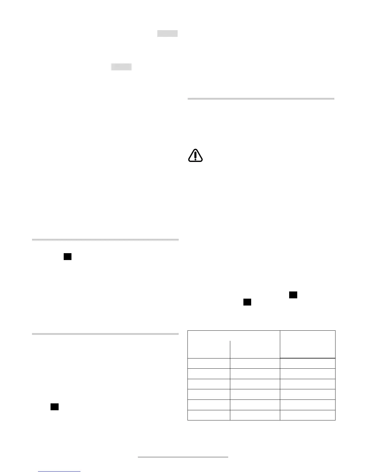
Maximum Work Piece Dimensions
45°-0
45° +
M
N
Mitre Angle Height x Width
[mm]
Mitre
(Horizontal)
Bevel
(Vertical)
0° 0° 85 x 305
45° 0° 85 x 216
0° 45° Left 50 x 305
0° 45° Right 32 x 305
45° 45° Left 50 x 216
45° 45° Right 32 x 216
O
P