English–161 609 929 F69 • (04.10) PS
Clamping Action of the Handle Clamp
(see Figure
)
Open the clamp 3.
Adjusting:
Turn the adjustment screws 70 with the Allen key 47
(SW 1.5) counter#clockwise to reduce the clamping
action or clockwise to increase the clamping action.
Always adjust the two screws to the same height.
Close the clamp 3 and check whether the desired
clamping action is achieved.
Angle Indicator (Horizontal)
(see Figure
)
Place the machine in the working position.
Rotate the saw table 16 to the detent 15 for 0°.
Checking:
The angle indicator 71 must be in alignment with the
0° mark of the scale 38.
Adjusting:
Loosen the attachment screw of the angle indicator
with the Phillips screwdriver 33 provided and align the
angle indicator along the 0° mark.
Retighten the attachment screw.
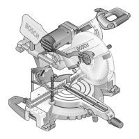
Fence
Place the electro#tool in the transport position.
Rotate the saw table 16 to the detent 15 for 0°.
Checking: (see Figure
)
Set the combination square to 90° and place it on the
saw table 16. The square must be flush with the fence
18 over its entire length.
Adjusting: (see Figure
)
Unscrew the knobs 20 of the fence extensions on both
sides completely out and loosen the adjustment screw
72 with the hex#head bit 33 (SW 4). Remove the fence
extensions.
Loosen all hex#head bolts 68 with the socket spanner
33 (SW 14). Rotate the fence 18 until the protractor is
flush over its entire length. Retighten the hex#head
bolts.
Remount the fence extensions. Tighten the adjust#
ment screws 72 only far enough so that the fence ex#
tensions can be easily slid.
X
Y
Z1
Z2
 Loading...
