30 | Electrical SM Series Heat Pump
SM Series Heat Pump6 720 220 406 (2013/1) Subject to change without prior notice
Safety Devices and the UPM Controller
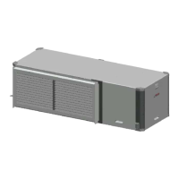
Figure # 96
[1] Board power indicator
[2] UPM Board LED indicator
[3] Water coil freeze protection temperature
selection
[4] Air coil freeze protection temperature selection
[5] UPM board settings
[6] Water coil freeze connection
[7] Air coil freeze connection
[8] LCD connection
[9] 24VAC power hot
[10] To compressor contactor
[11] High pressure switch connection
[12] Call for compressor
[13] Low pressure switch connection
[14] 24VAC power common
Each unit is factory provided with a Unit Protection
Module (UPM) that controls the compressor
operation and monitors the safety controls that
protect the unit.
Safety controls include the following:
• High pressure switch located in the refrigerant
discharge line and wired across the HPC
terminals on the UPM
• Low pressure switch located in the unit
refrigerant suction line and wired across
terminals LPC1 and LPC2 on the UPM.
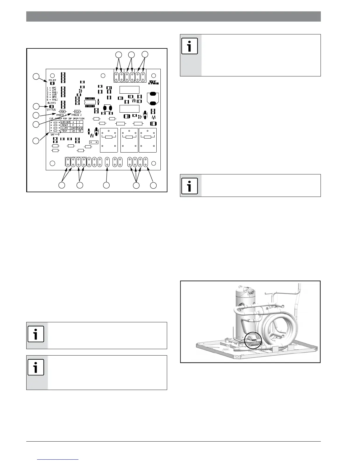
• Water side freeze protection sensor, mounted
close to condensing water coil, monitors
refrigerant temperature between condensing
water coil and thermal expansion valve. If
temperature drops below or remains at freeze
limit trip for 30 seconds, the controller will
shut down the compressor and enter into a
soft lockout condition. The default freeze limit
trip is 30°F, however this can be changed to
15°F by cutting the R30 or Freeze1 resistor
located on top of DIP switch SW1. (Figure #97)
Figure # 97
If the unit is being connected to a thermostat
with a malfunction light, this connection is made
at the unit malfunction output or relay.
If the thermostat is provided with a malfunction
light powered off of the common (C) side of the
transformer, a jumper between “R” and “COM”
terminal of “ALR” contacts must be made.
1
2
3
4
5
6
78
9
10
11
1213
If the thermostat is provided with a malfunction
light powered off of the hot (R) side of the
transformer, then the thermostat malfunction
light connection should be connected directly to
the (ALR) contact on the unit’s UPM board.
UPM Board Dry Contacts are Normally Open
(NO)
 Loading...