Electrical | 33SM Series Heat Pump
6 720 220 406 (2013/1)SM Series Heat Pump
ECM INTERFACE BOARD
Thermostat wiring is connected to the 10 pin
screw type terminal block on the lower center
portion of the ECM Interface Board. In addition to
providing a connecting point for thermostat wiring,
the interface board also translates thermostat
inputs into control commands for the Electronic
Commutated Motor (ECM) DC fan motor and
displays an LED indication of operating status. The
thermostat connections and their functions are as
follows:
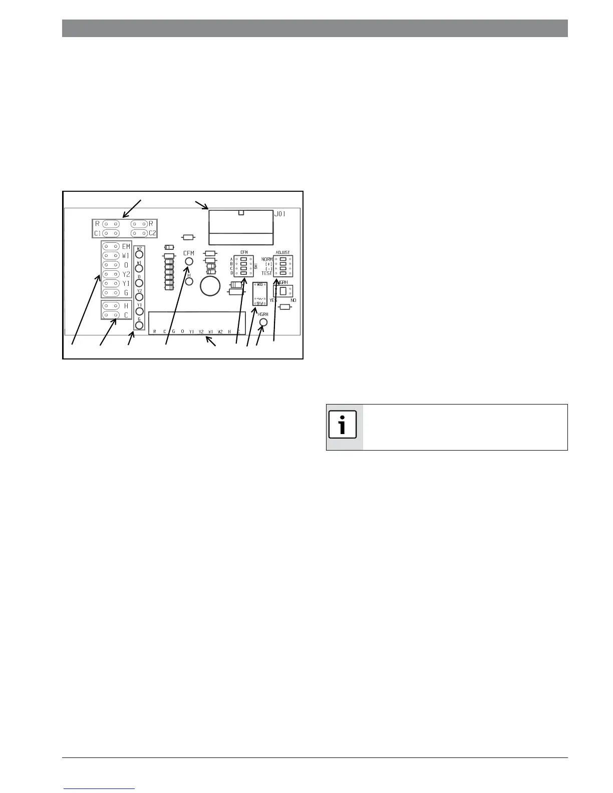
Figure # 100
[1] Motor harness plug
[2] Blower CFM adjustment
[3] Motor settings
[4] Dehumidification indication
[5] Thermostat digital inputs
[6] CFM count indicator
[7] Thermostat input status indication
[8] Reheat digital outputs
[9] Thermostat outputs
[10] 24 VAC
Just above the connector block is a single red LED
labeled CFM that will blink intermittently when the
unit is running and may flicker when the unit is off.
This LED indicates the air delivery of the blower at
any given time. Each blink of the LED represent
approximately 100 CFM of air delivery so if the LED
blinks 12 times, pauses, blinks 12 times, etc. the
blower is delivering approximately 1200 CFM.
To the right of the thermostat connection block is
a green LED labeled dehumidify. Just above and to
the right of the thermostat connection block are
two banks of DIP switches labeled ADJ and CFM.
The ADJ bank DIP switches are labeled NORM, (+),
(-), Test and HGHR position from the factory,
however, airflow can be increased (+) or
decreased (-) by 15% from the pre-programmed
setting by relocating the DIP switch in this section.
The TEST position is used to verify proper motor
operation. If a motor problem is suspected, move
the ADJ DIP switch to the TEST position and
energize G on the thermostat connection block. If
the motor ramps up to 100% power, then the
motor itself is functioning normally. Always
remember to replace the DIP switch to NORM, (+)
or (-) after testing and reset the unit thermostat to
restore normal operation.
HGRH switch is used to select operating mode
between units equipped with:
1. Re-heat coils
2. Cool to dehumidify
10
1
27
8
9
5
3
46
Y1 First Stage Compressor Operation
Y2 Second Stage Compressor Operation
G Fan
O Reversing Valve (energized in cooling)
W1 Auxiliary Electric Heat (runs in
conjunction with compressor)
EM/W2 Emergency Heat (electric heat only)
NC Transformer 24 VAC Common (extra
connection)
C1 Transformer 24 VAC Common
(primary connection)
R Transformer 24 VAC Hot
H Dehumidification Mode
CFM LED indication is an approximation. Utilize
conventional Test and Balance equipment for
accurate airflow measurement.
 Loading...