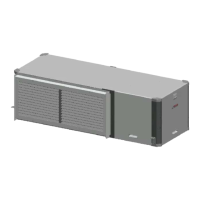
Greensource CDi Series TW Model
Greensource CDi Series TW Model8733954853 (2020/04)
12 | Post-Installation System Checkout
Subject to change without prior notice
POST-INSTALLATION SYSTEM
CHECKOUT
After completing the installation and before
energizing the unit, the following system checks
MUST be made:
1. Verify that the supply voltage to the heat pump
is in accordance with the nameplate ratings.
2. Make sure that all electrical connections are
tight and secure.
3. Check the electrical fusing and wiring for the
correct size.
4. Verify that the low-voltage wiring between the
thermostat and the unit is correct.
5. Verify that the water piping is complete and
correct.
6. Check that the water flow is correct and adjust
if necessary.
7. Verify that vibration isolation has been
provided.
8. Ensure the unit is serviceable.
9. Confirm that all access panels are secured in
place.
SYSTEM OPERATION
UNIT START-UP
1. Set the thermostat to the highest setting.
2. Set the thermostat system switch to “COOL.”
The reversing valve solenoid should energize.
The compressor should not run.
3. Reduce the thermostat setting approximately
five degrees below the room temperature.
4. Verify the heat pump is operating in the cooling
mode.
5. Turn the thermostat system switch to the
“OFF” position. The unit should stop running
and the reversing valve should de-energize.
6. Leave the unit off for approximately five
minutes to allow for system equalization.
7. Turn the thermostat to the lowest setting.
8. Set the thermostat switch to “HEAT.”
9. Increase the thermostat setting approximately
five degrees above the room temperature.
10. Verify the heat pump is operating in the heating
mode.
11. Set the thermostat to maintain the desired
space temperature.
12. Check for vibrations, leaks, etc.
Also see Initial Start-Up of a HRP System on page
#15.
SEQUENCE OF OPERATION
Cooling Mode
Energizing the “O” terminal energizes the unit
reversing valve thus placing the unit into cooling
mode. When the thermostat calls for first-stage
cooling (Y1) the loop pump or solenoid valve, if
present, is energized and the first stage of the
compressor capacity starts.
When the thermostat calls for second-stage
cooling (Y2) the second stage (or full-compressor
capacity) is initiated. Once the thermostat is
satisfied, the compressor shuts down accordingly.
Heating Mode
The first two stages of heating (Y1 & Y2) operate in
the same manner as cooling but with the reversing
valve de-energized. Once the thermostat is
satisfied, the compressor shuts down.
DANGER: Ensure the cabinet and electrical
box are properly grounded.
IMPORTANT:
• Always check incoming line-voltage power
supply and secondary control voltage for
adequacy. Transformer primaries are dual
tapped for 208 and 230 volts. Connect the
appropriate tap to ensure a minimum
secondary control voltage of 18 volts. 24
volts is ideal for best operation.
• Long-length thermostat and control wiring
leads may create voltage drop. Increase
wire gauge or up-size transformers may be
required to ensure minimum secondary
voltage supply.
• Bosch recommends the following
guidelines for wiring between a thermostat
and the unit: 18 GA up to 60 foot, 16 GA up
to 100 ft and 14 GA up to 140 ft.
• Do not apply additional controlled devices
to the control circuit power supply without
consulting the factory. Doing so may void
equipment warranties.
• Check with all code authorities on
installation criteria.
 Loading...