Installation | 7Greensource CDi Series TW Model
8733954853 (2020/04)Greensource CDi Series TW Model
Subject to change without prior notice
Always check carefully for water leaks and repair
appropriately. Units are equipped with female pipe
thread fittings. Consult Unit Dimensional Drawings
on page #41 and page #42.
Electrical
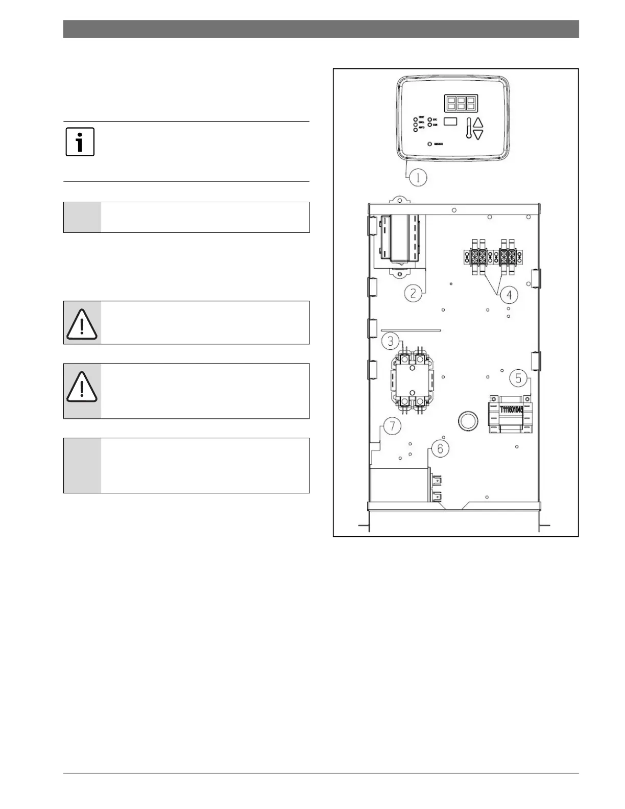
Refer to electrical component box layout. (See Fig. 4)
Properly-sized fuses or HACR circuit breakers must
be installed for branch circuit protection. See the
unit nameplate for maximum fuse or breaker size.
The unit is provided with a concentric knock-out
for attaching common trade sizes of conduit.
Route power supply wiring through this opening.
Always connect the ground lead to the grounding
lug provided in the control box and power leads to
the line side of compressor contactor as indicated
on the wiring diagrams starting on page #35.
Fig. 4 Electrical component box layout
[1] Unit-Mounted Controller
[2] Transformer
[3] Compressor Contractor
[4] Seven-Pin Terminal Block
[5] Pump/Valve Relay (Field-Installed Accessory)
[6] Compressor Capacitor
[7] Chassis Ground Lug
Teflon tape sealer should be used when
connecting water piping connections to the
units to insure against leaks and possible
heat exchanger fouling.
NOTICE: Do not overtighten the
connections.
WARNING: Field wiring must comply with
local and national electric codes.
WARNING: Power to the unit must be
within the operating voltage range indicated
on the unit’s nameplate or on the
performance data sheet.
NOTICE: Operation of unit on improper line
voltage or with excessive phase imbalance
will be hazardous to the unit, constitutes
abuse and may void the warranty.
 Loading...