Greensource CDi Series TW Model
Greensource CDi Series TW Model8733954853 (2020/04)
16 | Safety Devices and the UPM Controller
Subject to change without prior notice
SAFETY DEVICES AND THE UPM
CONTROLLER
TW025, TW035, TW049, and TW061 models are
equipped with the Unit Protection Module (UPM).
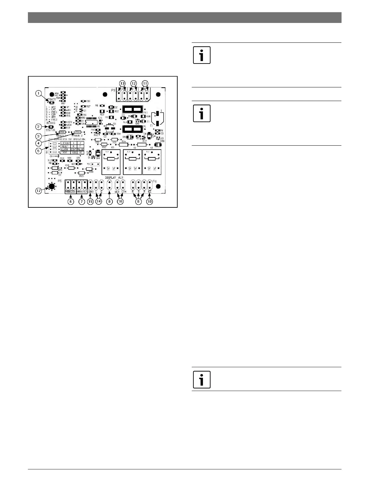
Fig. 9 UPM controller board
[1] Board Power Indicator
[2] UPM Status LED Indicator (Fault Status)
[3] Water Source Coil Freeze Protection
Temperature Selection (R30, FREEZE 1)
[4] Load Water Coil Freeze Protection
Temperature Selection (R24, FREEZE 2)
[5] UPM Board Settings
[6] Source Coax Freeze Connection (FREEZE 1)
[7] Load Coax Freeze Connection (FREEZE 2)
[8] LCD Unit Display Connection (Not Applicable
to Water-to-Water Units)
[9] 24VAC Power Input (R)
[10] Compressor Contact Output (Y1 Output)
[11] High-Pressure Switch Connection
[12] Call for Compressor (Y1 24VAC Input)
[13] Low-Pressure Switch Connection
[14] 24VAC Power Common (C)
[15] Condensate overflow Sensor (Not Applicable
to Water-to-Water Units)
[16] Dry Contact
[17] UPM Ground Standoff
The TW Series is equipped with the Unit Protection
Module (UPM) that controls the compressor
operation and monitors the safety controls that
protect the unit.
Safety controls include the following:
• High-pressure switch located in the refrigerant
discharge line and wired across the HPC
terminals on the UPM.
• Low-pressure switch located in the unit
refrigerant suction line and wired across
terminals LPC1 and LPC2 on the UPM.
• Water-side freeze protection sensor, mounted
close to condensing water coil, monitors
refrigerant temperature between condensing
water coil and thermal expansion valve. If
temperature drops below or remains at freeze
limit trip for 30 seconds, the controller will
shut down the compressor and enter into a
soft-lockout condition. The default freeze limit
trip is 26°F; however, this can be changed to
15°F by cutting the R30 or Freeze1 resistor
located on top of DIP switch SW1 (Refer to Fig.
9, item [3] for resistor location), refer to Fig.
10 for sensor location.
When a malfunction light is used for
diagnostic purposes, the connection is
made at the dry contact connection
terminals of the UPM board. Shown in
Fig. 9.
If the thermostat is provided with a
malfunction light powered off of the
common (C) side of the transformer, a
jumper between “R” and “COM” terminal of
“ALR” contacts must be installed.
The UPM Board Dry Contacts are Normally
Open (NO).
 Loading...