18
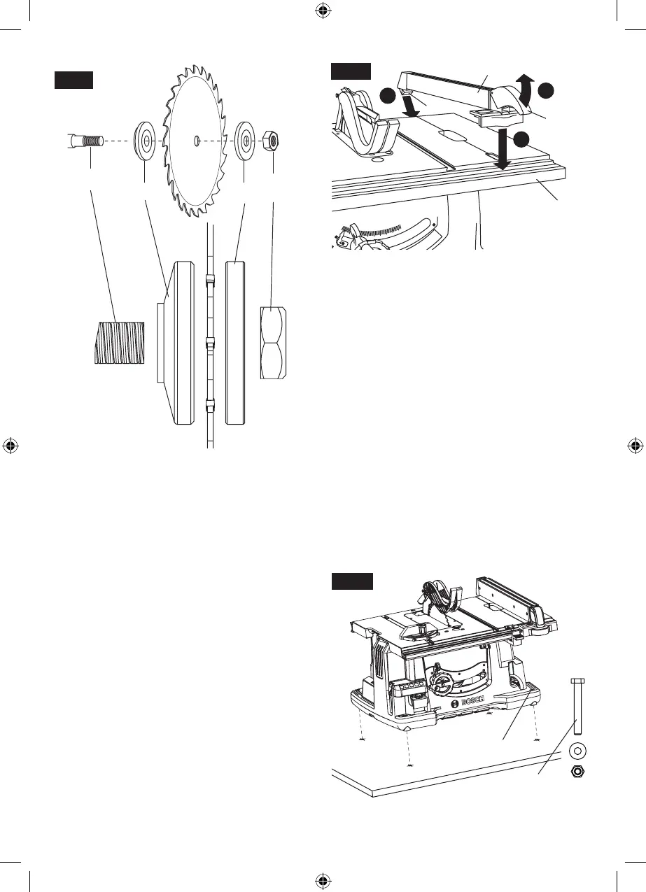
be removed or installed by sliding on or off ar-
bor shaft 6 (Fig. 18).
3. Assemble inner washer 7 and new blade as
shown in figure 18, making certain the TEETH
OF THE BLADE ARE POINTING DOWN AT
THE FRONT OF THE TABLE. NOTE: The
printing on different saw blades is not always
on the same side.
4. Assemble outer washer 5 and arbor nut 3 as
shown in figure 17. While holding arbor lock le-
ver 2 securely, tighten arbor nut 3 clockwise
with the wrench 4. (Fig. 16).
5. Position table insert 21 in pocket of table so
tabs 21a on table insert 21 are in slots in pock-
et of table and push down and secure in place
using table insert lock 22 (Fig.4, page 13).
ATTACHING RIP FENCE
1. Raise rip fence handle 1, so holding clamp 2 is
out far enough to fit on the table 3 and into “V”
groove located on the back of rear rail (Fig. 19).
2. Position the rip fence 4 over table 3 holding up
the front end, first engage holding clamp 2 with
rear rail.
3. Lower front end onto front rail 5.
MOUNTING THE TABLE SAW
If table saw is to be used in a permanent location,
it should be fastened securely to a firm support-
ing surface such as a stand or workbench, using
the four mounting holes 6 (Fig. 19).
1. If mounting to a workbench, the base should
be bolted securely using 5/16” hex bolts (not
included) through mounting holes 6.
Hint: If workbench is 3/4” thick, bolts will have
to be at least 3-1/2” long - if workbench is 1-1/2”
thick, bolts should be at least 4-1/2” long.
2. Locate and mark where the saw is to be mount-
ed, relative to holes in the base of the tool.
3. Drill four (4) 3/8” diameter holes through work-
bench.
4. Place table saw on workbench aligning holes
in base with holes drilled in workbench.
5. Insert four (4) 5/16” dia. bolts through holes in
base and supporting surface; then secure with
(4) 5/16” flat washers and (4) 5/16” hex nuts.
3
5
7
6
Fig. 18
B
C
A
Fig. 19
1
5
3
2
4
6
5/16” HEX BOLT,
WASHER &
HEX NUT (X4)
Fig. 20
1600A009XC 09-15.indb 18 9/14/15 1:51 PM