Do you have a question about the Bosch Intellic EFAS-4.10 and is the answer not in the manual?
Identifies the intended users of the workshop manual, including authorized personnel.
Explains the meaning of special symbols used for emphasis and warnings.
Outlines binding EU regulations for tachograph use and driver working conditions.
Covers the European Agreement concerning the work of crews in international road transport.
Discusses supplementary national legislation applicable in EU member states.
Lists relevant standards and regulations that the EFAS Tachograph complies with.
Explains the mandatory transition to second-generation smart tachographs and requirements.
Details specific vehicle types or operations exempted from mandatory tachograph installation.
Describes the components and data storage capabilities of digital tachograph systems.
Outlines obligations for drivers and vehicle owners regarding tachograph usage.
Introduces tachograph smart-cards used for user identification and data storage.
Details the four types of smart-cards (Driver, Workshop, Company, Control) and their functions.
Provides essential rules and guidelines for handling and maintenance of tachograph smart-cards.
Explains how to access, display, print, and archive recorded tachograph data.
Describes how to view various parameters displayed on the tachograph unit.
Provides guidelines for handling and preserving tachograph printouts to ensure readability.
Details the procedures and requirements for downloading and archiving data from the mass memory.
Explains how to manage data readouts, especially when replacing a tachograph unit.
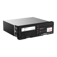
Provides an overview of the EFAS tachograph's hardware components and activation conditions.
Describes the six operating keys on the front of the EFAS tachograph and their functions.
Explains the function and operation of the two card readers integrated into the EFAS tachograph.
Details the alphanumeric monochrome LCD display of the EFAS tachograph and its configuration.
Explains the meaning of the red warning light and acoustic signals indicating operational states.
Describes the printer paper container and how to refill it with a new paper roll.
Details the service port for calibration, configuration, and data download operations.
Guides users on navigating and operating the EFAS tachograph using its menu system.
Explains how different smart-card types affect the tachograph's operating modes.
Illustrates how combinations of inserted smart-cards determine the tachograph's operational mode.
Covers essential steps and checks before installing the EFAS tachograph in a vehicle.
Outlines checks to perform upon receiving the EFAS tachograph for transport damage.
Provides guidelines for storing the EFAS tachograph correctly to prevent damage.
Details crucial visual checks of the device and its components before installation.
Explains the information contained on the EFAS tachograph's type label.
Discusses different hardware and software versions of the EFAS tachograph available.
Lists historical hardware and software versions of the EFAS tachograph.
Specifies checks to perform on the EFAS tachograph before commencing installation.
Guides on the proper handling of the EFAS tachograph during installation into a vehicle bay.
Details the connector panel at the back of the EFAS device and its connection layout.
Provides detailed pin assignments for the EFAS tachograph's connectors A and B.
Explains fuse protection requirements for the positive and negative poles of the tachograph's power supply.
Guides on installing and connecting the motion sensor to the EFAS tachograph.
Details the procedure for mounting the EFAS tachograph unit into its designated bay in the vehicle.
Explains the conditions that activate the EFAS tachograph and its different operating states.
Outlines when and how to replace the internal buffer battery of the EFAS tachograph.
Provides step-by-step instructions for safely removing the internal buffer battery.
Details the correct procedure for installing a new internal buffer battery into the EFAS tachograph.
Explains the sealing procedure for the EFAS tachograph after installation or battery replacement.
Describes necessary preparation and parameter configuration before activating the EFAS tachograph.
Guides on the initial activation process of the EFAS tachograph, including motion sensor pairing.
Explains the 'Technical Data' printout before the tachograph is activated.
Details the activation process using a workshop card and PIN entry.
Covers the steps and data entry required for initial installation calibration after activation.
Explains how to enter the vehicle's official number plate and registration details.
Lists various other purposes for calibration of the EFAS tachograph.
Details how to manually pair the motion sensor with the tachograph if automatic pairing fails.
Explains the installation and connection of the DSRC module for remote communication.
Covers the placement and mounting requirements for the DSRC module according to EU regulations.
Describes how to connect the DSRC module to the EFAS tachograph via the CAN bus.
Guides on how to adjust the internal clock settings, including date, time, and time zone.
Details the procedure for setting the date and time on the EFAS tachograph, including UTC synchronization.
Explains how to set the time zone for accurate local time display.
Describes the settings for automatic switching between daylight saving and standard time.
Explains how to modify the date display format on the tachograph.
Details how to program automatic activity settings for drivers upon ignition changes.
Explains the irreversible function to block older generation tachograph cards.
Describes how to enable or disable the remote data download function via CAN-C.
Lists functions available when the FMS unit is attached and activated.
Provides instructions on how to replace the printer paper roll.
Explains how access rights affect parameter reading and modification via the service port.
Details the defined ranges and lengths for parameter values as per ISO 16844-7.
Lists key parameters for adapting EFAS to vehicle types and external devices.
Sets the vehicle's nominal voltage (12V or 24V) for proper detection of voltage fluctuations.
Configures the main CAN bus for communication with instrument clusters and diagnostic devices.
Configures the auxiliary CAN bus for additional functions like remote data transfer or DSRC module.
Determines if the tachograph can be activated by CAN messages while in standby mode.
Sets the source for resetting the trip distance, either via CAN bus or tachograph menu.
Controls how the display and keypad back-lighting are managed, either via CAN or analog input.
Defines the operating modes for input A2 used for controlling display and keypad illumination.
Configures PWM settings for lighting control when input A2 is an analogue PWM input.
Sets a factor for calculating the output shaft speed, crucial for transmission compatibility.
Selects the source for recording engine speed, either CAN bus or pulse signal.
Sets the constant for calculating engine speed from pulse input, used when not receiving via CAN.
Configures the serial interface on connector D7 for diagnostics or e-tachometer connection.
Configures the serial interface on connector D8 for diagnostics, FMS, or information interface.
Monitors pulse output B7 for short-circuits, important for door locks and over-speed control.
Configures the pulse output D6 for signaling different states or speed-coding.
Enables or disables monitoring of CAN 'reset' messages from bus subscribers.
Adjusts the transmission interval for the TCO1 message, affecting vehicle speed and driver activity data.
Configures the FMS service for remote data download via CAN message.
Explains how the tachograph automatically detects and sets certain parameters upon installation.
Lists the default preset values for legally prescribed vehicle parameters upon delivery.
Details preparatory checks and actions required before performing calibration.
Recommends a visual inspection of the tachograph's front for damage before removal.
Outlines checks for the installation plaque's integrity and the condition of seals and connections.
Explains how to read out data using the workshop's resources via the service interface.
Advises checking and replacing the internal buffer battery if the last check was over 12 months ago.
Specifies requirements for test equipment needed for calibrating the EFAS tachograph.
Guides on the calibration process, including checks, connections, and test runs.
Refers to section 10.6.15 for instructions on testing the GNSS module.
Refers to section 10.6.16 for instructions on testing the DSRC module.
Describes the procedure and requirements for conducting a test drive for calibration verification.
Explains the fixing and content requirements for the installation plaque after calibration.
Introduces the monitoring of system functions and classification of events, malfunctions, and instructions.
Differentiates between three types of error codes (EFT, DTC, Service ID) used for diagnosis.
Explains how events and malfunctions are displayed in different operating modes and contexts.
Describes how events and malfunctions appear in the tachograph's operational display.
Details how events and malfunctions are shown before activation or during calibration.
Explains the 'Service!' message indicating a serious internal malfunction.
Outlines a general procedure for diagnosing and resolving displayed events or malfunctions.
Lists tools like test equipment and the EFAS Service Tool for diagnosing faults.
Provides an overview of the supported integrated test functions for various components.
Explains how to perform a printer test to assess print quality and form feed.
Notes that EFAS checks card condition during operation and identifies errors via DTCs.
Describes tests for optical inspection of the display, including chessboard and inverse patterns.
Details the keyboard test for checking key functionality and detecting defects.
Reports general hardware faults and lists associated DTC codes.
Tests the functionality of the warning light and the integrated acoustic alarm.
Checks the engine-speed detection configuration and source.
Verifies the voltage level of the on-board power supply at the EFAS connector.
Inspects digital inputs and outputs at the EFAS connector panel for proper wiring and signal levels.
Verifies the calculated rotational speed of the output shaft based on sensor pulses and calibration factor.
Verifies the motion sensor interface, including voltage, current, pulse frequency, and communication status.
Performs a check on the internal back-up battery and displays its measured value.
Checks the functions of the pulse outputs (B6, B7, B8, D6) for signal frequency and voltage.
Initiates a test to determine if the GNSS function is operating correctly.
Tests the DSRC module to confirm proper functioning of the remote communication equipment.
Verifies communication on CAN A and CAN C buses using the EFAS Service Tool.
Provides step-by-step instructions for safely removing the EFAS tachograph from a vehicle.
Guides on how to extract a smart-card that is jammed in the tachograph slot.
Refers to section 6.2.6 for details on replacing the buffer battery.
Outlines repairs that must be performed by the manufacturer and information needed for repair requests.
Details the steps and considerations for decommissioning a digital tachograph, including data handling and disposal.
Explains the manufacturer's warranty terms and conditions for the EFAS device.
Lists circumstances under which the EFAS device warranty becomes invalidated.
Provides a summary table of event fault types (EFTs) and their corresponding service IDs.
Lists events and faults with their meanings and troubleshooting measures, organized by Service ID.
Presents an overview of Diagnostic Trouble Codes (DTCs) and their associated Service IDs.
Explains how to print or display the last 100 service IDs from the EFAS tachograph.
Guides on creating a support file using the EFAS Service Tool for technical assistance.
Explains the two independent CAN interfaces (main and expansion bus) of the EFAS tachograph.
Details the importance and correct setting of CAN bus terminating resistors for stable communication.
Lists the types of data transferred via the CAN bus main vehicle bus and upon request.
Outlines essential parameters for configuring the CAN bus to meet specific vehicle requirements.
Describes the two bidirectional serial ports (D7, D8) on the EFAS tachograph for diagnostics and information.
Explains the information interface protocol for cyclical data transmission.
Details the standard UDS protocol for diagnostics and parameter reading via the K-line interface.
Discusses the pulse outputs used for controlling external displays and encoding speed/distance.
Explains how speed is coded via outputs B6 and B7, including short-circuit monitoring.
Describes the configuration options for speed-coding output D6, including alternative states.
Details the distance encoding output B8, also known as '4 pulse/m' output.
Explains the recording of vehicle speed in defined speed ranges over time.
Describes the logging of engine speed based on pulse signals or CAN bus data.
Details the logging of status changes at digital inputs D1 and D2 with time-stamps.
Provides notes and explanations regarding the symbols and warnings in the driver's times summary printout.
Lists the necessary hardware, software, and smart-cards for performing a software update.
Explains how to view device information like hardware and software versions.
Guides on how to request and download the latest tachograph software from the manufacturer.
Details the process of transferring the downloaded software to the EFAS tachograph.
Describes how to verify a successful software update and the necessary subsequent recalibration.
Lists national/regional abbreviations and their corresponding European time zone offsets.
Provides a comprehensive list of the EFAS tachograph's technical specifications and data.
Illustrates the hierarchical structure of the EFAS tachograph's menu system.
Explains symbols for persons, their activities, and the tachograph's operating modes.
Lists symbols associated with different types of tachograph smart-cards.
Defines symbols representing driver activities like standby, driving, resting, and working.
Provides symbols for identifying various components of the EFAS tachograph.
Explains symbols indicating special conditions relevant to tachograph operation.
Lists miscellaneous pictograms used in tachograph displays and printouts.
Details symbols and their meanings for common error messages displayed by the tachograph.
Explains symbols representing different time intervals like daily, weekly, or fortnight.
Illustrates combinations of symbols and their meanings in tachograph displays and printouts.
Defines symbols related to driving activities and time tracking.
Lists symbols used to denote different types of printouts generated by the tachograph.
Explains symbols representing various events that can occur during tachograph operation.
Details symbols indicating different types of malfunctions detected by the tachograph.
Explains symbols used for marking manual driver entries in the tachograph.
Lists messages that may appear during the printing process.
| Brand | Bosch |
|---|---|
| Model | Intellic EFAS-4.10 |
| Category | Measuring Instruments |
| Language | English |