4 | Prepare Data Base
42/76 Engine_Control_Unit_MS_6.x_Manual Bosch Motorsport
The functionality of the ETC diagnosis and the fault responses are described in the tech-
nical documents, handed over to the customer together with the system. Each driver must
be briefed regarding the system description. Further information you will find in docu-
ment “SICHERHEITSHINWEISE-Systemanforderungen zum Betrieb eines Bosch Engineer-
ing GmbH EGas-Systems” or can be enquired at Bosch Motorsport.
The customer is responsible for the activation of all ETC‐relevant diagnosis and for their
correct parameterization. By disregarding this information the functionality of the ECU and
the safety cannot be ensured.
Notice: For detailed information see function description ETC
The usual route of ETC determines the drivers input measuring the pedal position and
transferring this leading signal via functionality options into the control of an electrical
throttle actuator. Pedal- and actuator positions are generally measured in a secondary re-
dundant way to verify the reliability of the function. To activate the system, first verify the
signal tolerances and error messages by moving acceleration pedal and throttle actuator
manually. An inactive system usually is the result of inverted wired sensor signals or actu-
ator controls. Calibrate the pedal- and throttle positions.
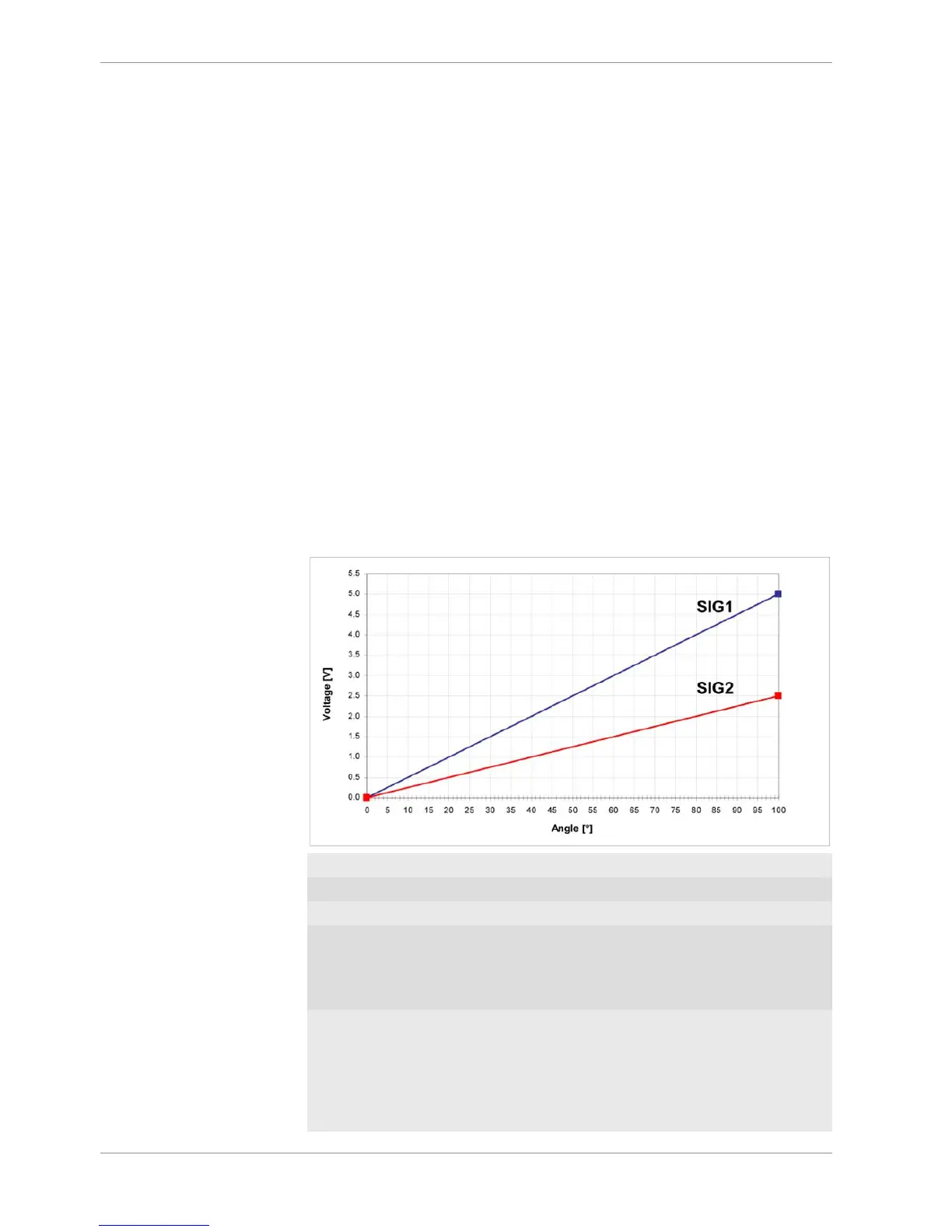
Verification of acceleration pedal signals:
The mathematic value of voltage pedal signal 1 - 2*voltage pedal signal 2 has to be below
0.5 V or below value of “UAPSCM_MAX”.
Signal principle of an acceleration pedal sensor:
uaps_a Voltage APS potentiometer a
uaps_b Voltage APS potentiometer b
aps Acceleration pedal position
UAPS_MIN, UAPS_MAX: Minimum and maximum accepted sensor
voltage. Set to approx. 200 mV/4,800 mV.
Check if the uaps(x) outputs are changing
when the pedal is moved.
CWAPSADJ Codeword to adjust acceleration pedal sig-
nal:
0 = calibration inactive
1 = calibrate release pedal
2 = calibrate full-pressed pedal