BoschRexrothAG, RE 91485-01-B/2021-11-18
48/72 A10FZO, A10VZO, A10FZG and A10VZG series 10 | Installation
L
L
1
B
B
A
A
NG3 … 18 NG21 … 63
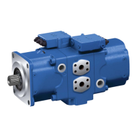
Abb� 27: Port overview A10FZO, SAE flange ports (port plate 02)
L
L
R
L
1
S
X
M
B
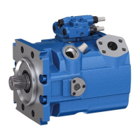
Abb� 28: Port overview A10VZO, DRG control, SAE flange ports (port plate 22)
Tabelle 25: Ports A10FZO
Ports
1)
p
max
[bar]
2)
State
3)
B(A)
7)
Working port (high-pressure series) 350 O
A(B)
7)
Suction port (standard pressure series) 10 O
L Drain port 2 O
4)
L
1
Drain port (only NG 21 to 63) 2 X
4)
Tabelle 26: Ports A10VZO
Ports
1)
p
max
[bar]
2)
State
3)
B Working port (high-pressure series) 350 O
S Suction port (standard pressure series) 10 O
L Drain port 2 O
4)
L
1
Drain port 2 X
4)
X Pilot pressure 350 O
X
5)
Pilot pressure 280 O
M
B
6)
Measuring port pressure in B 350 X
1) The measuring system and thread size can be found in the installation drawing.
2) Depending on the application, momentary pressure peaks can occur. Keep this in mind when
selecting measuring devices and fittings.
3) O=Must be connected (plugged on delivery)
X = Plugged (in normal operation)
4) Depending on the installation position, L or L
1
must be connected
(see chapter7.3 "Installation position A10FZO, A10VZO" on page33).
5) Only for DG control.
6) Only for port plate22 and 32.
7) Depending on the direction of rotation, please observe the information in this manual.
Port overview
A10FZO
Port overview
A10VZO

 Loading...