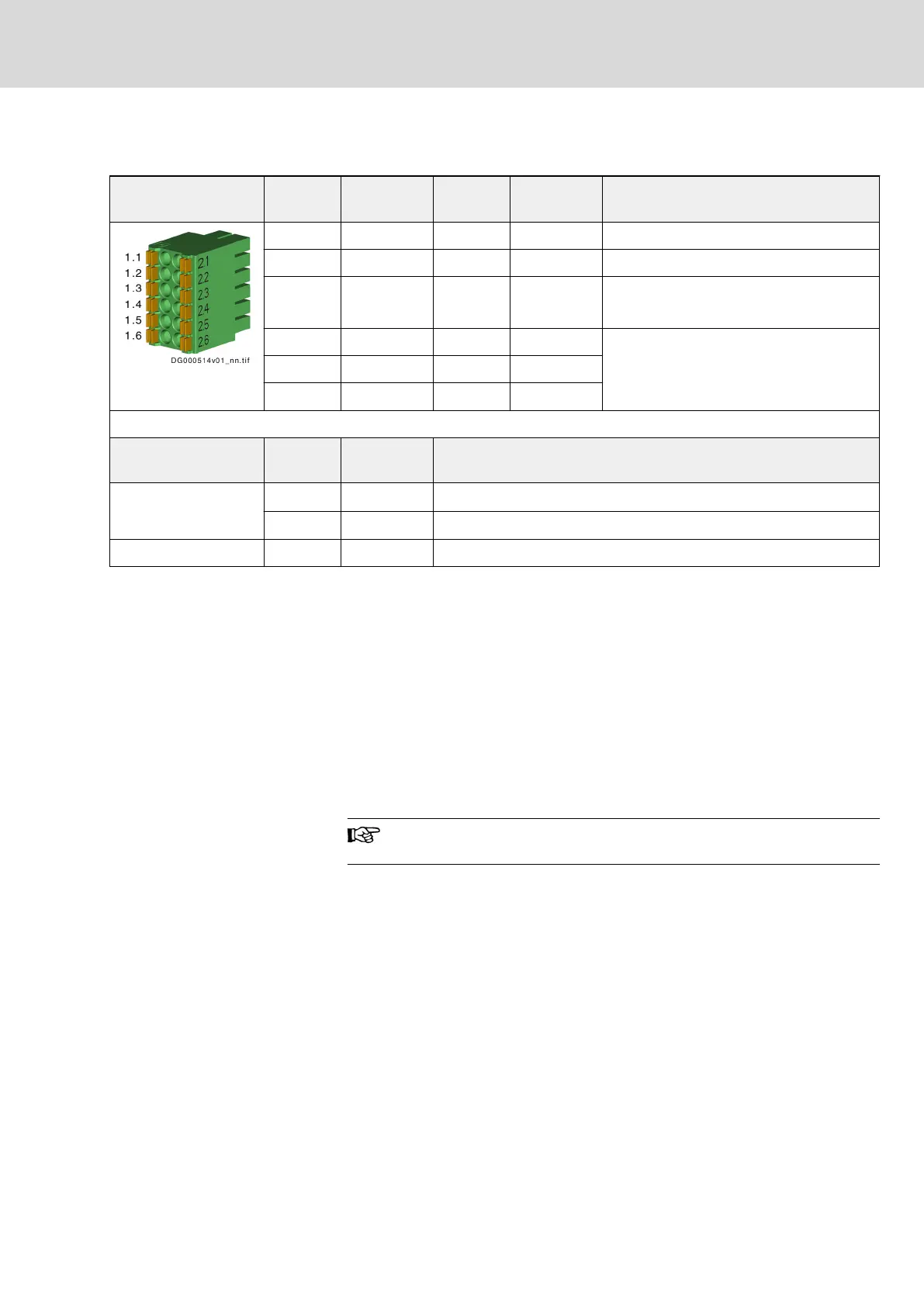
6.12 X36, digital inputs/outputs, analog outputs
View Connec‐
tion
Signal name Connec‐
tion
Signal name Function
1.1 OA_1 2.1 OA_2 Analog output
1.2 GND_A1 2.2 GND_A2 GND reference of analog output
1.3 GND_100 2.3 GND_100 GND reference
Connection for inner cable shield
1.4 I_17/O_3 2.4 I_20/O_6 Digital input/output
1.5 I_18/O_4 2.5 I_21/O_7
1.6 I_19/O_5 2.6 I_22/O_8
Spring terminal (con‐
nector)
Unit min. max.
Connection cable
Stranded wire
mm
2
0.2 1.5
AWG 24 16
Stripped length mm - 10
Tab. 6-14: Function, pin assignment, properties
GND Reference
X33/1.2 is the GND reference of the digital inputs and outputs.
Shield connection
chapter 9.3 "Analog inputs/outputs: Shield connection" on page 130
Technical data
chapter 8.7.2 "Digital inputs" on page 115
chapter 8.7.3 "Digital Outputs" on page 119
chapter 8.10 "Analog Output" on page 125
The connection point is only available at double-axis control sec‐
tions.
DOK-INDRV*-CXX02******-PR03-EN-P Bosch Rexroth AG 59/143
IndraDrive Control Sections CSB02, CSE02, CSH02, CDB02
On-board connection points
Courtesy of CMA/Flodyne/Hydradyne ▪ Motion Control ▪ Hydraulic ▪ Pneumatic ▪ Electrical ▪ Mechanical ▪ (800) 426-5480 ▪ www.cmafh.com