8 Technical data - functions
8.1
EC - standard encoder evaluation
8.1.1 Supported encoder systems
Supported Encoder Systems
Encoder systems with a supply voltage of 5 and 12 volt:
● MSM motor encoder
● MSK motor encoder
● Sin-cos encoder 1V
pp
; HIPERFACE®
● Sin-cos encoder 1V
pp
; EnDat 2.1; (EnDat 2.2 in preparation)
● Sin-cos encoder 1V
pp
; with reference track
● 5V-TTL square-wave encoder; with reference track
● SSI
● Combined encoder for SSI (combination of SSI and sin-cos encoder
1V
pp
)
● Resolver (resolvers are not supported if an optional "Safe Motion" safety
technology is available at the same time.)
● Hall sensor box SHL02.1
● Digital Hall sensor in conjunction with Hall sensor adapter box SHL03.1
8.1.2 Encoder type
IndraDyn S MSM motors (5V supply voltage)
Properties
Encoder systems of the MSM motors are digital encoder systems that can be
evaluated in absolute form.
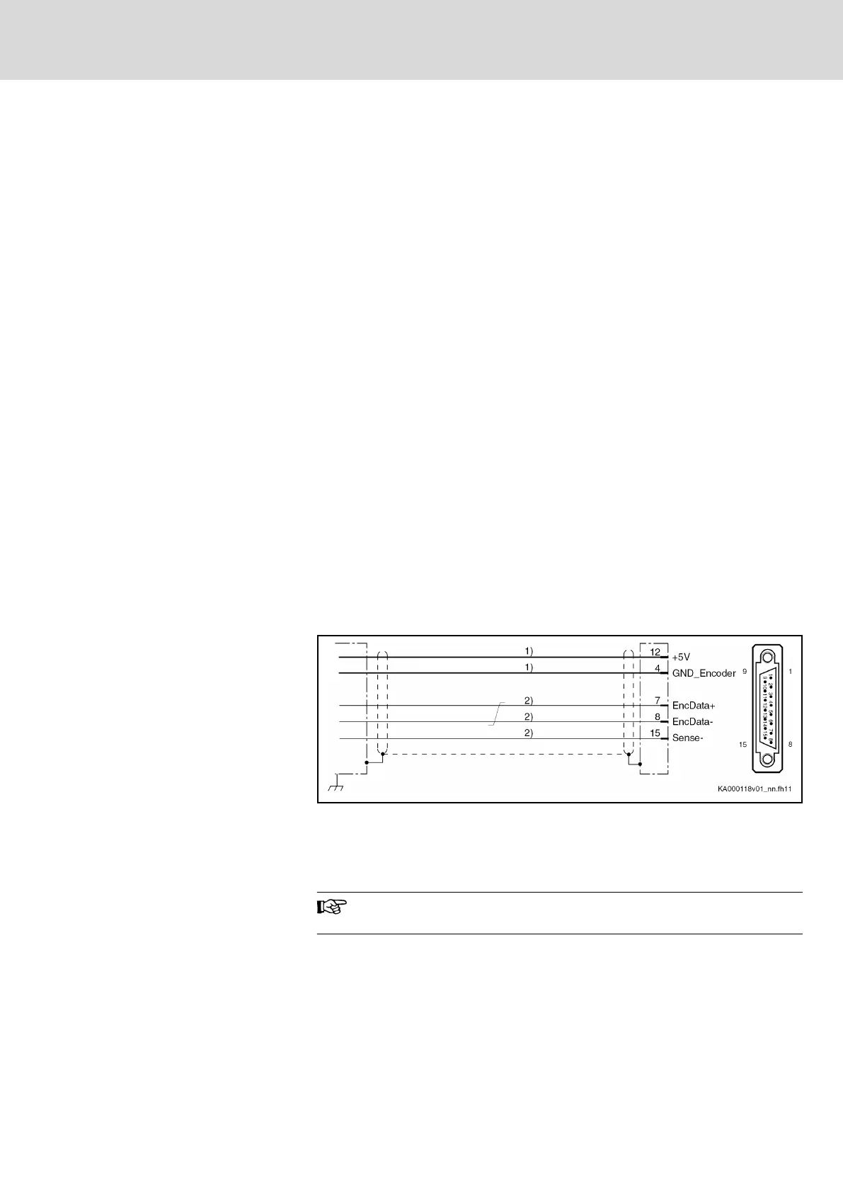
Connection diagram
1) Line cross section ≥ 0.5 mm²; observe allowed encoder cable
length
2) Line cross section ≥ 0.14 mm²
Fig. 8-1: EC connection diagram with encoder system of IndraDyn S MSM mo‐
tors
For direct
connection to the encoder system, use our RKG0033
cable.
Power supply
5 V (the voltage is made available via the EC interface)
Technical
specification of the power supply: See chapter "5 V power supply"
on page 92
Cable length
40 m at most
DOK-INDRV*-CXX02******-PR03-EN-P Bosch Rexroth AG 79/143
IndraDrive Control Sections CSB02, CSE02, CSH02, CDB02
Technical data - functions
Courtesy of CMA/Flodyne/Hydradyne ▪ Motion Control ▪ Hydraulic ▪ Pneumatic ▪ Electrical ▪ Mechanical ▪ (800) 426-5480 ▪ www.cmafh.com