Disclaimer of Warranties:
This manual contains test procedures and test information obtained by an ASE Certified Master Technician with
known good test equipment on real vehicles, your tests may vary due to your equipment or technician procedures.
No warranty can be made from the ideas presented due to personal testing procedures, nor does the author or
anyone connected with him assume responsibilities or liabilities. The use o
f this manual is conditional on the
acceptance of this disclaimer. If the terms of this disclaimer are not acceptable, please return this manual.
A
utomotive Video, Inc.
6280 Arc Way
Ft. Myers, FL 33966
1-800-71-TRAIN (1800-718-7246)
fax: 1-239-561-9111
www.auto-video.com
Content authored for Automotive Video Inc. by Heritage Technical LLC, Cochranville, PA. Copyrighted © in 2010 by
Heritage Technical LLC. No portion of this manual may be copied, altered, or reproduced without written permission
of the author.
TABLE OF CONTENTS
OVERVIEW . . . . . . . . . . . . . . . . . . . . . . . . . . . . . . . . . . . . . . . . . . . . . . . .2
COMMON CONNECTORS AND COMPONENTS . . . . . . . . . . . . . . . . . .4
GETTING STARTED . . . . . . . . . . . . . . . . . . . . . . . . . . . . . . . . . . . . . . . . .4
SETTING UP THE TECH 2 . . . . . . . . . . . . . . . . . . . . . . . . . . . . . . . . . . . .5
Power Up And Display . . . . . . . . . . . . . . . . . . . . . . . . . . . . . . . . . . . .5
H
OW TO FIND THE ONLINE MANUALS . . . . . . . . . . . . . . . . . . . . . . . . .6
UPDATING THE SOFTWARE VERSION . . . . . . . . . . . . . . . . . . . . . . . . .7
Tech 2 Update Procedures . . . . . . . . . . . . . . . . . . . . . . . . . . . . . . . .8
N
ATIONAL AUTOMOTIVE SERVICE TASK FORCE (NASTF) . . . . . . . .11
REGISTERING AN ACCOUNT WITH TIS2WEB . . . . . . . . . . . . . . . . . . .13
TIS2WEB OVERVIEW . . . . . . . . . . . . . . . . . . . . . . . . . . . . . . . . . . . . . . .15
SETTING UP TECH 2 VIEW (T2 VIEW) . . . . . . . . . . . . . . . . . . . . . . . . .16
MAIN MENU NAVIGATION . . . . . . . . . . . . . . . . . . . . . . . . . . . . . . . . . .17
POWERTRAIN NAVIGATION MENU . . . . . . . . . . . . . . . . . . . . . . . . . . .18
Building A Vehicle In The Tech 2 . . . . . . . . . . . . . . . . . . . . . . . . . . .18
1. Select the year of the vehicle . . . . . . . . . . . . . . . . . . . . . . . . .20
2. Select the vehicle type . . . . . . . . . . . . . . . . . . . . . . . . . . . . . . .21
3. Select the vehicle make . . . . . . . . . . . . . . . . . . . . . . . . . . . . . .21
4. Select the product line . . . . . . . . . . . . . . . . . . . . . . . . . . . . . . .22
5. Select the engine type . . . . . . . . . . . . . . . . . . . . . . . . . . . . . . .22
P
OWERTRAIN NAVIGATION MENU REVIEW . . . . . . . . . . . . . . . . . . . .23
Diagnostic Menu . . . . . . . . . . . . . . . . . . . . . . . . . . . . . . . . . . . . . . . .23
Diagnostic trouble codes (DTCs) . . . . . . . . . . . . . . . . . . . . . . . . .24
Data display . . . . . . . . . . . . . . . . . . . . . . . . . . . . . . . . . . . . . . . . . .26
Special functions . . . . . . . . . . . . . . . . . . . . . . . . . . . . . . . . . . . . . .27
Using the CANDi module . . . . . . . . . . . . . . . . . . . . . . . . . . . . . . . .29
C
LEARING DIAGNOSTIC TROUBLE CODES (DTCS) . . . . . . . . . . . . . .31
VEHICLE CONTROL SYSTEMS . . . . . . . . . . . . . . . . . . . . . . . . . . . . . . .32
BCM Data . . . . . . . . . . . . . . . . . . . . . . . . . . . . . . . . . . . . . . . . . . . . . .32
Q
UICK SNAPSHOT . . . . . . . . . . . . . . . . . . . . . . . . . . . . . . . . . . . . . . . . .34
Recording Data . . . . . . . . . . . . . . . . . . . . . . . . . . . . . . . . . . . . . . . . .34
P
OWERTRAIN NAVIGATION . . . . . . . . . . . . . . . . . . . . . . . . . . . . . . . . .35
Power Steering Control Module . . . . . . . . . . . . . . . . . . . . . . . . . . . .35
Data Display . . . . . . . . . . . . . . . . . . . . . . . . . . . . . . . . . . . . . . . . . . . .36
T
ECH 2 VIEW . . . . . . . . . . . . . . . . . . . . . . . . . . . . . . . . . . . . . . . . . . . . .38
Special Functions . . . . . . . . . . . . . . . . . . . . . . . . . . . . . . . . . . . . . . .38
Module ID Information . . . . . . . . . . . . . . . . . . . . . . . . . . . . . . . . . . .38
S
PECIAL FUNCTIONS . . . . . . . . . . . . . . . . . . . . . . . . . . . . . . . . . . . . . .39
Body Control Module . . . . . . . . . . . . . . . . . . . . . . . . . . . . . . . . . . . . .39
Instrument Panel Cluster . . . . . . . . . . . . . . . . . . . . . . . . . . . . . . . . .41
Lighting Systems . . . . . . . . . . . . . . . . . . . . . . . . . . . . . . . . . . . . . . . .42
EVAP Systems . . . . . . . . . . . . . . . . . . . . . . . . . . . . . . . . . . . . . . . . . .43
BASIC COMPONENT TESTS . . . . . . . . . . . . . . . . . . . . . . . . . . . . . . . . .44
Diagnostic Trouble Codes (DTCs) . . . . . . . . . . . . . . . . . . . . . . . . . . .44
R
EPROGRAMMING . . . . . . . . . . . . . . . . . . . . . . . . . . . . . . . . . . . . . . . .45
Getting Prepared . . . . . . . . . . . . . . . . . . . . . . . . . . . . . . . . . . . . . . . .45
Vehicle Setup . . . . . . . . . . . . . . . . . . . . . . . . . . . . . . . . . . . . . . . . . . .45
Performing The Reprogram . . . . . . . . . . . . . . . . . . . . . . . . . . . . . . .47
Reprogramming Calibration Information . . . . . . . . . . . . . . . . . . . .50
T
ECH 2 VIEW . . . . . . . . . . . . . . . . . . . . . . . . . . . . . . . . . . . . . . . . . . . . .52
Oil Life Monitor Reset . . . . . . . . . . . . . . . . . . . . . . . . . . . . . . . . . . . .52
E
VAP SERVICE BAY TESTING . . . . . . . . . . . . . . . . . . . . . . . . . . . . . . . .54
Setting Up . . . . . . . . . . . . . . . . . . . . . . . . . . . . . . . . . . . . . . . . . . . . . .54
C
HECKING FOR LEAKS . . . . . . . . . . . . . . . . . . . . . . . . . . . . . . . . . . . . .55
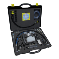
EVAP Testing Using A Smoke Machine And The Tech 2 . . . . . . . .55
G
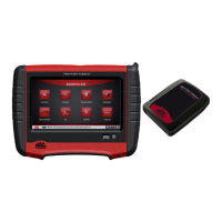
M MDI INTERFACE . . . . . . . . . . . . . . . . . . . . . . . . . . . . . . . . . . . . . . .56
Overview . . . . . . . . . . . . . . . . . . . . . . . . . . . . . . . . . . . . . . . . . . . . . . .56
Online Information . . . . . . . . . . . . . . . . . . . . . . . . . . . . . . . . . . . . . .58
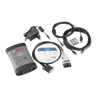
What Is Included In The Kit . . . . . . . . . . . . . . . . . . . . . . . . . . . . . . .59
G
M MDI VS THE MASTERTECH VCI . . . . . . . . . . . . . . . . . . . . . . . . . . .60
What Is The Difference . . . . . . . . . . . . . . . . . . . . . . . . . . . . . . . . . . .60
G
M MDI SOFTWARE . . . . . . . . . . . . . . . . . . . . . . . . . . . . . . . . . . . . . . .60
Setting Up The GDS Software And GM MDI Manager . . . . . . . . .60
G
DS SOFTWARE . . . . . . . . . . . . . . . . . . . . . . . . . . . . . . . . . . . . . . . . . .61
Basic Navigation . . . . . . . . . . . . . . . . . . . . . . . . . . . . . . . . . . . . . . . .61
Data Display . . . . . . . . . . . . . . . . . . . . . . . . . . . . . . . . . . . . . . . . . . .66
Vehicle & Module Diagnosis . . . . . . . . . . . . . . . . . . . . . . . . . . . . . .67
R
EVIEW . . . . . . . . . . . . . . . . . . . . . . . . . . . . . . . . . . . . . . . . . . . . . . . . . .68
MDI Tool And GDS Software . . . . . . . . . . . . . . . . . . . . . . . . . . . . . .68
1-800-71-TRAIN (1-800-718-7246) OR www.auto-video.com
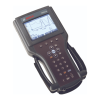
BOSCH TECH 2
Presented by Bob Pattengale
1